- 您現(xiàn)在的位置:買賣IC網(wǎng) > PDF目錄362681 > EM6152V30 (EM Microelectronic) 5V Automotive Regulator with Windowed Watchdog PDF資料下載
參數(shù)資料
| 型號: | EM6152V30 |
| 廠商: | EM Microelectronic |
| 英文描述: | 5V Automotive Regulator with Windowed Watchdog |
| 中文描述: | 汽車與5V的穩(wěn)壓器窗口看門狗 |
| 文件頁數(shù): | 8/12頁 |
| 文件大?。?/td> | 529K |
| 代理商: | EM6152V30 |
R
EM6152
Timer Clearing and
RES
Action
Copyright 2006, EM Microelectronic-Marin SA
rev. B / 06.06
8
www.emmicroelectronic.com
The watchdog circuit monitors the activity of the processor.
If the user’s software does not send a pulse to the
TCL
input within the programmed open window timeout period a
short watchdog
RES
pulse is generated which is equal to
T
WDR
(see Fig. 6).
With the open window constraint, new security is added to
conventional watchdogs by monitoring both software cycle
time and execution. Should software clear the watchdog too
quickly (incorrect cycle time) or too slowly (incorrect
execution) it will cause the system to be reset. If software is
stuck in a loop which includes the routine to clear the
watchdog then a conventional watchdog would not make a
system reset even though the software is malfunctioning;
the circuit would make a system reset because the
watchdog would be cleared too quickly.
If no
TCL
signal is applied before the closed and open
windows expire,
RES
will start to generate square waves of
period T
WDRP
= T
CW
+ T
OW
+ T
WDR
. The watchdog will remain
in this state until the next
TCL
falling edge appears during
an open window, or until a fresh power-up sequence. The
system enable output, EN , can be used to prevent critical
control functions being activated in the event of the system
going into this failure mode (see section “Enable-
EN
Output”).
The
RES
output must be pulled up to V
OUTPUT
even if the
output is not used by the system (see Fig 8).
Combined Voltage and Timer Action
The combination of voltage and timer actions is illustrated
by the sequence of events shown in Fig. 6. On power-up,
when the voltage at V
IN
reaches V
REF
, the power-on-reset,
POR, delay is initialized and holds
RES
active for the time
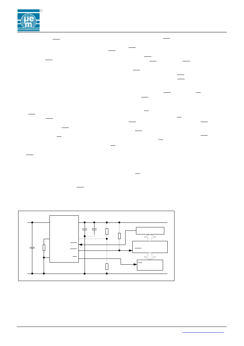
Typical Application
of the POR delay. A
TCL
pulse will have no effect until this
power-on-reset delay is completed. When the risk exists that
TCL
temporarily floats, e.g. during T
POR
, a pull-up to
V
OUTPUT
is required on that pin. After the POR delay has
elapsed,
RES
goes inactive and the watchdog timer starts
acting. If no
TCL
pulse occurs,
RES
goes active low for a
short time T
WDR
after each closed and open window period.
A
TCL
pulse coming during the open window clears the
watchdog timer. When the
TCL
pulse occurs too early
(during the closed window),
RES
goes active and a new
timeout sequence starts. A voltage drop below the V
REF
level for longer than typically 3
μ
s overrides the timer and
immediately forces
RES
active and EN inactive. Any
further
TCL
pulse has no effect until the next power-up
sequence has completed.
Enable -
EN
Output
The system enable output, EN , is inactive always when
RES
is active and remains inactive after a
RES
pulse until
the watchdog is serviced correctly 3 consecutive times (i.e.
the
TCL
pulse must come in the open window). After three
consecutive services of the watchdog with
TCL
during the
open window, the EN goes active low.
A malfunctioning system would be repeatedly reset by the
watchdog. In a conventional system critical motor controls
could be energized each time reset goes inactive (time
allowed for the system to restart) and in this way the
electrical motors driven by the system could function out of
control. The circuit prevents the above failure mode by using
the EN output to disable the motor controls until software
has successfully cleared the watchdog three times (i.e. the
system has correctly re-started after a reset condition).
The important parameters of the 22
μ
F input capacitor are an effective series resistance lower than 3
Ω
and a resonant
frequency above 500 kHz.
Fig. 8
Regulated Voltage (5V)
V
SS
GND
Unregulated
Voltage
INPUT
EM6152
OUTPUT
R
OSC
RES
EN
TCL
V
IN
RES
Microprocessor
Motor
controls
EN
Address decoder
R
1
R
2
22uF
100nF
100k
Ω
22uF
+
+
相關PDF資料 |
PDF描述 |
|---|---|
| EM6152V30PS16B | 5V Automotive Regulator with Windowed Watchdog |
| EM6152V30SO8A | 5V Automotive Regulator with Windowed Watchdog |
| EM6152V30SO8B | 5V Automotive Regulator with Windowed Watchdog |
| EM6152V50 | 5V Automotive Regulator with Windowed Watchdog |
| EM6152V50PS16B | 5V Automotive Regulator with Windowed Watchdog |
相關代理商/技術參數(shù) |
參數(shù)描述 |
|---|---|
| EM620F32-45LF | 制造商:EMLSI 制造商全稱:Emerging Memory & Logic Solutions Inc 功能描述:256K x8 bit Super Low Power and Low Voltage Full CMOS Static RAM |
| EM620F32-45LL | 制造商:EMLSI 制造商全稱:Emerging Memory & Logic Solutions Inc 功能描述:256K x8 bit Super Low Power and Low Voltage Full CMOS Static RAM |
| EM620F32-85LF | 制造商:EMLSI 制造商全稱:Emerging Memory & Logic Solutions Inc 功能描述:256K x8 bit Super Low Power and Low Voltage Full CMOS Static RAM |
| EM620F32-85LL | 制造商:EMLSI 制造商全稱:Emerging Memory & Logic Solutions Inc 功能描述:256K x8 bit Super Low Power and Low Voltage Full CMOS Static RAM |
| EM620F32B-45LF | 制造商:EMLSI 制造商全稱:Emerging Memory & Logic Solutions Inc 功能描述:256K x8 bit Super Low Power and Low Voltage Full CMOS Static RAM |
發(fā)布緊急采購,3分鐘左右您將得到回復。