- 您現(xiàn)在的位置:買賣IC網(wǎng) > PDF目錄67419 > FAR-F5CE-942M50-K216-U SAW FILTER PDF資料下載
參數(shù)資料
| 型號: | FAR-F5CE-942M50-K216-U |
| 元件分類: | 聲表面波濾波器 |
| 英文描述: | SAW FILTER |
| 文件頁數(shù): | 23/41頁 |
| 文件大?。?/td> | 458K |
| 代理商: | FAR-F5CE-942M50-K216-U |
第1頁第2頁第3頁第4頁第5頁第6頁第7頁第8頁第9頁第10頁第11頁第12頁第13頁第14頁第15頁第16頁第17頁第18頁第19頁第20頁第21頁第22頁當前第23頁第24頁第25頁第26頁第27頁第28頁第29頁第30頁第31頁第32頁第33頁第34頁第35頁第36頁第37頁第38頁第39頁第40頁第41頁

3
F5/F6 Series (K2 type)
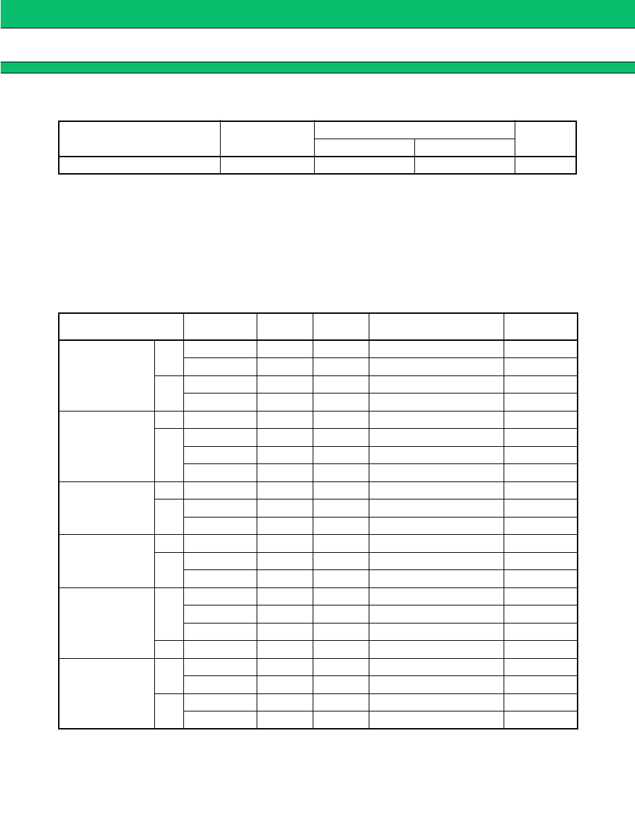
s RECOMMENDED OPERATING CONDITIONS
WARNING: The recommended operating conditions are required in order to ensure the normal operation of the
piezoelectric device. All of the device’s electrical characteristics are warranted when the device is
operated within these ranges.
Always use piezoelectric devices within their recommended operating condition ranges.Operation
outside these ranges may adversely affect reliability and could result in device failure.
No warranty is made with respect to uses , operating conditions, or combinations not represented on
the data sheet. Users considering application outside the listed conditions are advised to contact their
FUJITSU representatives beforehand.
s STANDARD FREQUENCIES
Parameter
Symbol
Value
Unit
Min.
Max.
Operating temperature
Ta
–30
+85
°C
System
Center freq.
(MHz)
B/W
(MHz)
Part
symbol
Part number
Remarks
AMPS
/TDMA
/CDMA
Tx
836.5
25
FAR-F5CE-836M50-K225
Low loss type
836.5
25
30
FAR-F5CE-836M50-K230
High Att. type
Rx
881.5
25
87
FAR-F5CE-881M50-K287
Low loss type
881.5
25
10
FAR-F5CE-881M50-K210
High Att. type
GSM
Tx
902.5
25
13
FAR-F5CE-902M50-K213
Rx
947.5
25
33
FAR-F5CE-947M50-K233
Ultra low loss
947.5
25
14
FAR-F5CE-947M50-K214
Low loss type
947.5
25
28
FAR-F5CE-947M50-K228
High Att. type
EGSM
Tx
897.5
35
26
FAR-F5CE-897M50-K226
Rx
942.5
35
88
FAR-F5CE-942M50-K288
Low loss type
942.5
35
16
FAR-F5CE-942M50-K216
PDC800
(20 MHz passband
width standard)
Tx
950.0
20
01
FAR-F5CE-950M00-K201
Rx
820.0
20
02
FAR-F5CE-820M00-K202
Low loss type
820.0
20
04
FAR-F5CE-820M00-K204
High Att. type
cdmaOne
Tx
906.0
38
11
FAR-F5CE-906M00-K211
Low loss type
906.0
38
19
FAR-F5CE-906M00-K219
906.0
38
15
FAR-F5CE-906M00-K215
High Att. type
Rx
851.0
38
12
FAR-F5CE-851M00-K212
PDC1.5 G
Tx
1441.0
24
23
FAR-F6CE-1G4410-K223
Low loss type
1441.0
24
20
FAR-F6CE-1G4410-K220
Rx
1489.0
24
FAR-F6CE-1G4890-K224
Low loss type
1489.0
24
21
FAR-F6CE-1G4890-K221
相關PDF資料 |
PDF描述 |
|---|---|
| FAR-F5CE-906M00-K219-W | SAW FILTER |
| FAR-F5CE-906M00-K219-V | SAW FILTER |
| FAR-F5CE-906M00-K219-U | SAW FILTER |
| FAR-F5CE-906M00-K215-W | SAW FILTER |
| FAR-F5CE-906M00-K215-V | SAW FILTER |
相關代理商/技術參數(shù) |
參數(shù)描述 |
|---|---|
| FAR-F5CE-942M50-K216V | 制造商:未知廠家 制造商全稱:未知廠家 功能描述:Surface Acoustic Wave Filter |
| FAR-F5CE-942M50-K216W | 制造商:未知廠家 制造商全稱:未知廠家 功能描述:Surface Acoustic Wave Filter |
| FAR-F5CE-942M50-K216-W | 制造商:FUJITSU 功能描述: |
| FAR-F5CE-942M50-K237 | 制造商:FUJITSU 制造商全稱:Fujitsu Component Limited. 功能描述:Piezoelectric SAW BPF (700 to 1700 MHz) |
| FAR-F5CE-942M50-K237-U | 制造商:FUJITSU 制造商全稱:Fujitsu Component Limited. 功能描述:Piezoelectric SAW BPF (700 to 1700 MHz) |
發(fā)布緊急采購,3分鐘左右您將得到回復。