- 您現(xiàn)在的位置:買賣IC網(wǎng) > PDF目錄67429 > FC250H1 (LINEAGE POWER LLC) DC-DC REG PWR SUPPLY MODULE PDF資料下載
參數(shù)資料
| 型號(hào): | FC250H1 |
| 廠商: | LINEAGE POWER LLC |
| 元件分類: | 電源模塊 |
| 英文描述: | DC-DC REG PWR SUPPLY MODULE |
| 封裝: | MODULE-20 |
| 文件頁(yè)數(shù): | 5/20頁(yè) |
| 文件大小: | 564K |
| 代理商: | FC250H1 |
第1頁(yè)第2頁(yè)第3頁(yè)第4頁(yè)當(dāng)前第5頁(yè)第6頁(yè)第7頁(yè)第8頁(yè)第9頁(yè)第10頁(yè)第11頁(yè)第12頁(yè)第13頁(yè)第14頁(yè)第15頁(yè)第16頁(yè)第17頁(yè)第18頁(yè)第19頁(yè)第20頁(yè)
Lineage Power
13
Data Sheet
April 2008
18 Vdc to 36 Vdc Input, 24 Vdc Output; 250 W
FC250H1 Power Module: dc-dc Converter;
Thermal Considerations (continued)
Introduction (continued)
The temperature at this location should not exceed
100 °C. The maximum case temperature can be limited
to a lower value for extremely high reliability. The output
power of the module should not exceed the rated power
for the module as listed in the Ordering Information table.
For additional information about these modules, refer to
the
Thermal Management for FC- and FW-Series 250
W—300 W Board-Mounted Power Modules Technical
Note (TN96-009EPS).
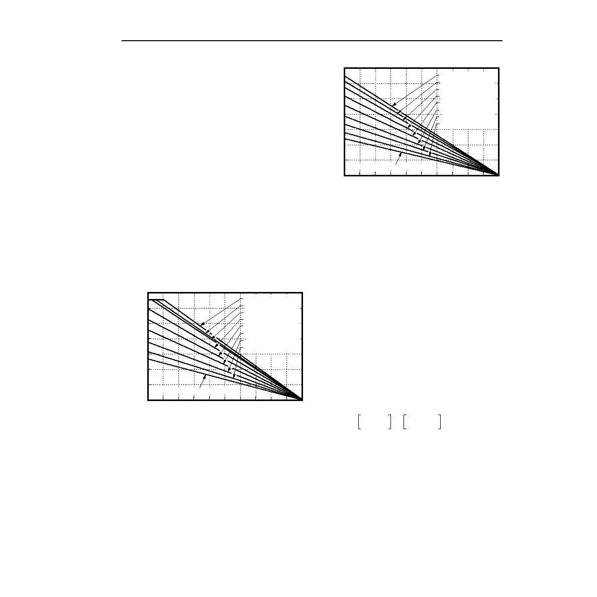
Heat Transfer Without Heat Sinks
Derating curves for forced-air cooling without a heat
sink are shown in Figures 19 and 20. These curves can
set of operating conditions. For example, if the unit with
airow along its length dissipates 20 W of heat, the
correct airow in a 40 °C environment is 1.0 m/s
(200 ft./min.).
8-1315 (C)
Figure 19. Convection Power Derating with No Heat
Sink; Airow Along Width; Transverse
Orientation
8-1314 (C)
Figure 20. Convection Power Derating with No Heat
Sink; Airow Along Length;
Longitudinal Orientation
Heat Transfer with Heat Sinks
The power modules have through-threaded, M3 x 0.5
mounting holes, which enable heat sinks or cold plates
to be attached to the module. The mounting torque
must not exceed 0.56 N/m (5 in./lb.). For a screw
attachment from the pin side, the recommended hole
size on the customer’s PWB around the mounting
holes is 0.130 ± 0.005 inches. If a larger hole is used,
the mounting torque from the pin side must not exceed
0.25 N/m (2.2 in./lb.).
Thermal derating with heat sinks is expressed by using
the overall thermal resistance of the module. Total mod-
ule thermal resistance (
θca) is dened as the maximum
case temperature rise (
TC, max) divided by the module
power dissipation (PD):
The location to measure case temperature (TC) is
shown in Figure 18. Case-to-ambient thermal resis-
tance vs. airow for various heat sink congurations is
shown in Figure 21 and Figure 22. These curves were
obtained by experimental testing of heat sinks, which
are offered in the product catalog.
0
10
203040
100
0
40
60
70
LOCAL AMBIENT TEMPERATURE, TA (
°C)
POWER
DISSIPATION,
P
D
(W)
30
20
10
90
80
70
60
50
4.0 m/s (800 ft./min.)
3.5 m/s (700 ft./min.)
3.0 m/s (600 ft./min.)
2.5 m/s (500 ft./min.)
2.0 m/s (400 ft./min.)
1.5 m/s (300 ft./min.)
1.0 m/s (200 ft./min.)
0.5 m/s (100 ft./min.)
0.1 m/s (20 ft./min.) NAT. CONV.
0
10
203040
100
0
40
60
70
LOCAL AMBIENT TEMPERATURE, TA (
°C)
POWER
DISSIPATION,
P
D
(W)
30
20
10
90
80
70
60
50
4.0 m/s (800 ft./min.)
3.5 m/s (700 ft./min.)
3.0 m/s (600 ft./min.)
2.5 m/s (500 ft./min.)
2.0 m/s (400 ft./min.)
1.5 m/s (300 ft./min.)
1.0 m/s (200 ft./min.)
0.5 m/s (100 ft./min.)
50
0.1 m/s (20 ft./min.) NAT. CONV.
θca
TC max
,
PD
---------------------
TC
TA
–
()
PD
------------------------
==
相關(guān)PDF資料 |
PDF描述 |
|---|---|
| FC250H1 | 1-OUTPUT 250 W DC-DC REG PWR SUPPLY MODULE |
| FC250H1 | 1-OUTPUT 250 W DC-DC REG PWR SUPPLY MODULE |
| FC30 | SPECIALTY ANALOG CIRCUIT, PBGA14 |
| FC30TR | SPECIALTY ANALOG CIRCUIT, PBGA14 |
| FCD4A14CCB | IMAGE SENSOR, UUC19 |
相關(guān)代理商/技術(shù)參數(shù) |
參數(shù)描述 |
|---|---|
| FC250R | 制造商:MA-COM 制造商全稱:M/A-COM Technology Solutions, Inc. 功能描述:Power Module:dc-dc Converter; 18 Vdc to 36 Vdc Input, 28 Vdc Output; 250 W |
| FC250R1 | 制造商:MA-COM 制造商全稱:M/A-COM Technology Solutions, Inc. 功能描述:Power Module:dc-dc Converter; 18 Vdc to 36 Vdc Input, 28 Vdc Output; 250 W |
| FC2528 | 制造商: 功能描述: 制造商:undefined 功能描述: |
| FC252U | 制造商:AB 功能描述:POT2.5K ALLEN BRADLEY S7D7B |
| FC255 | 制造商:未知廠家 制造商全稱:未知廠家 功能描述:THIN SMD LOW / MEDIUM FREQUENCY CRYSTAL UNIT |
發(fā)布緊急采購(gòu),3分鐘左右您將得到回復(fù)。