- 您現(xiàn)在的位置:買賣IC網(wǎng) > PDF目錄371743 > FS781BT MISCELLANEOUS CLOCK GENERATOR|TSSOP|8PIN|PLASTIC PDF資料下載
參數(shù)資料
| 型號: | FS781BT |
| 英文描述: | MISCELLANEOUS CLOCK GENERATOR|TSSOP|8PIN|PLASTIC |
| 中文描述: | 雜項時鐘發(fā)生器| TSSOP封裝| 8引腳|塑料 |
| 文件頁數(shù): | 6/13頁 |
| 文件大?。?/td> | 103K |
| 代理商: | FS781BT |

LOW EMI SPECTRUM SPREAD CLOCK
Cypress Semiconductor Corporation
525 Los Coches St.
Milpitas, CA 95035. Tel: 408-263-6300, Fax: 408-263-6571
http://www.cypress.com
Document#: 38-07029 Rev. **
05/07/2001
Page 6 of 13
APPROVED
PRODUCT
FS781/82/84
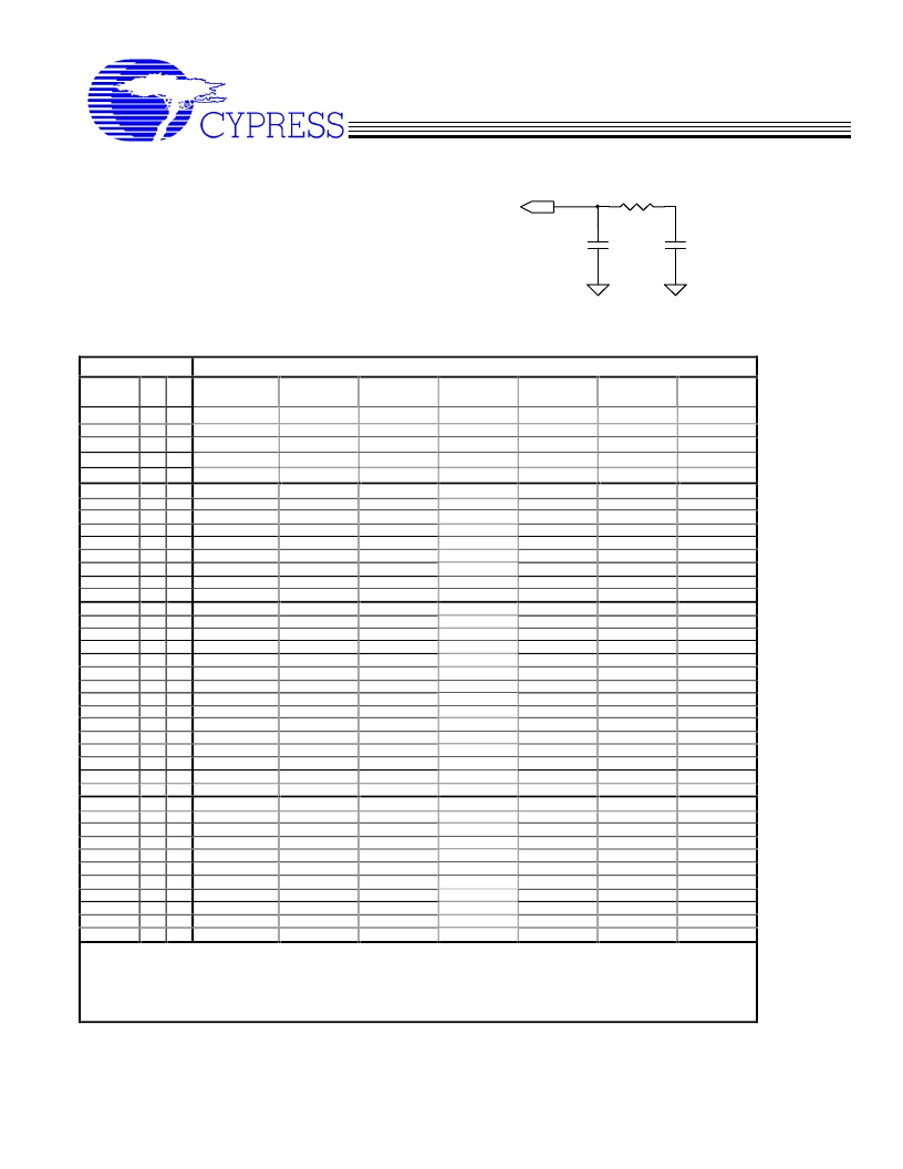
Loop Filter Selection Chart
The following table provides a list of recommended
loop filter values for the FS781/2/4. The FS78x is
divided into 4 ranges and operates at both 3.3 and
5.0 VDC. The loop filter at the right is representative
of the loop filter components in the table below.
FS781/2/4 Recommended Loop Filter Values.
C7 (pF.) @ +3.3 VDC +/- 5% (R6 = 3.3K)
Input
(MHz)
1
0
(note 3)
6
0
0
10,000/1000
8
0
0
10,000/330
10
0
0
1040
12
0
0
830
14
0
0
580
16
0
1
10000
S
S
BW = 1.0%
BW = 1.5%
(note 3)
1550
990
680
420
230
980
BW = 2.0%
(note 3)
910
820
460
300
200
760
BW = 2.5%
(note 3)
780
640
360
220
160
580
BW = 3.0%
(note 3)
700
520
300
200
140
470
BW = 3.5%
(note 3)
640
450
240
190
100
410
BW = 4.0%
(note 3)
560
400
210
170
80
385
20
22
24
26
28
30
32
34
36
38
40
42
44
46
48
0
0
0
0
0
0
0
1
1
1
1
1
1
1
1
1
1
1
1
1
1
1
0
0
0
0
0
0
0
0
1000
960
920
660
470
470
330
10000
2200
1500
960
940
950
900
790
730
640
400
300
230
180
170
860
820
690
600
620
680
580
440
470
410
250
220
180
140
120
640
620
520
420
380
400
270
260
390
270
210
180
150
120
100
520
470
410
340
275
250
220
210
320
230
180
150
130
100
82
430
400
340
280
230
210
190
180
220
200
160
140
100
80
68
380
330
290
220
210
190
180
160
190
180
150
120
70
60
47
330
290
240
160
180
170
165
140
52
54
56
58
60
62
64
1
1
1
1
1
1
1
0
0
0
0
0
0
1
470
470
445
430
295
270
1180
325
270
250
210
185
220
860
220
200
185
165
150
150
560
185
170
150
130
120
120
410
155
140
120
100
100
100
340
135
130
85
65
90
82
290
120
100
47
33
82
68
230
66
68
70
72
74
76
78
80
82
1
1
1
1
1
1
1
1
1
1
1
1
1
1
1
1
1
1
1180
1180
1120
1160
1110
1000
910
900
900
760
750
740
780
770
720
670
620
540
560
500
470
470
470
440
270
260
250
350
320
370
300
280
240
210
210
210
260
260
300
250
230
210
190
190
190
220
230
240
220
210
190
170
170
170
210
210
170
190
190
170
160
156
150
Notes:
1.
2.
3.
4.
If the value selected from the above chart is not a standard, use the next available larger value.
All Bandwidth
’
s indicated above are total peak-to-peak spread. 1% = +0.5% to
–
0.5%. 4% = +2.0% to
–
2.0%.
If C8 is not listed in the chart for a particular BW and Freq., it is not used in the loop filter.
Contact factory for LF (Loop Filter) values less than 1.0 % BW.
Table 7
C8
R6
C7
LF (pin 4)
相關PDF資料 |
PDF描述 |
|---|---|
| FS781BZB | MISCELLANEOUS CLOCK GENERATOR|SOP|8PIN|PLASTIC |
| FS782BT | MISCELLANEOUS CLOCK GENERATOR|TSSOP|8PIN|PLASTIC |
| FS782BZB | MISCELLANEOUS CLOCK GENERATOR|SOP|8PIN|PLASTIC |
| FS784BT | MISCELLANEOUS CLOCK GENERATOR|TSSOP|8PIN|PLASTIC |
| FS784BZB | MISCELLANEOUS CLOCK GENERATOR|SOP|8PIN|PLASTIC |
相關代理商/技術參數(shù) |
參數(shù)描述 |
|---|---|
| FS781BZB | 制造商:未知廠家 制造商全稱:未知廠家 功能描述:MISCELLANEOUS CLOCK GENERATOR|SOP|8PIN|PLASTIC |
| FS782 | 制造商:CYPRESS 制造商全稱:Cypress Semiconductor 功能描述:Low EMI Spectrum Spread Clock |
| FS782BT | 制造商:未知廠家 制造商全稱:未知廠家 功能描述:MISCELLANEOUS CLOCK GENERATOR|TSSOP|8PIN|PLASTIC |
| FS782BZB | 制造商:未知廠家 制造商全稱:未知廠家 功能描述:MISCELLANEOUS CLOCK GENERATOR|SOP|8PIN|PLASTIC |
| FS784 | 制造商:CYPRESS 制造商全稱:Cypress Semiconductor 功能描述:Low EMI Spectrum Spread Clock |
發(fā)布緊急采購,3分鐘左右您將得到回復。