- 您現(xiàn)在的位置:買賣IC網(wǎng) > PDF目錄65260 > GMR7590C-21S3C (GLENAIR INC) 21 CONTACT(S), FEMALE, D MICROMINIATURE CONNECTOR, SOLDER, SOCKET PDF資料下載
參數(shù)資料
| 型號: | GMR7590C-21S3C |
| 廠商: | GLENAIR INC |
| 元件分類: | D-微型連接器 |
| 英文描述: | 21 CONTACT(S), FEMALE, D MICROMINIATURE CONNECTOR, SOLDER, SOCKET |
| 文件頁數(shù): | 2/4頁 |
| 文件大?。?/td> | 498K |
| 代理商: | GMR7590C-21S3C |
2006 Glenair, Inc.
CAGE Code 06324/0CA77
Printed in U.S.A.
GLENAIR, INC. 1211 AIR WAY GLENDALE, CA 91201-2497 818-247-6000 FAX 818-500-9912
www.glenair.com
C-33
E-Mail: sales@glenair.com
Micro-D
PCB
A
B
C
D
E
F
G
H
J
K
L
M
N
P
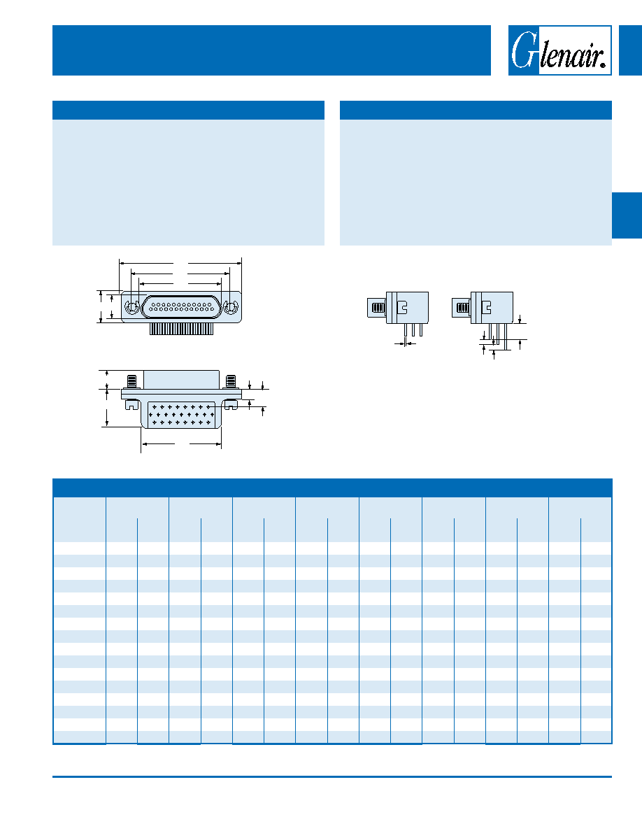
GMR7590C CoNNECtoR DIMENSIoNS
Layout
A Max.
B
C Max.
D Max.
E Max.
F
G Max.
H
In.
mm.
In .
± .005
mm.
± 0.13
In .
mm.
In .
mm.
In.
mm.
In .
± .003
mm.
± 0.08
In.
mm.
In.
± .010
mm.
±0.25
9P
.785 19.94
.565
14.35 .335
8.51
.185
4.70
.310
7.87
.183
4.65
.400 10.16
9S
.785 19.94
.565
14.35 .400
10.16
.251
6.38
.310
7.87
.195
4.95
.400 10.16
15P
.935 23.75
.715
18.16 .485
12.32
.185
4.70
.310
7.87
.183
4.65
.400 10.16
.550 13.97
15S
.935 23.75
.715
18.16 .550
13.97
.251
6.38
.310
7.87
.195
4.95
.400 10.16
.550 13.97
21P
1.085 27.56
.865
21.97 .635
16.13
.185
4.70
.310
7.87
.183
4.65
.400 10.16
.700 17.78
21S
1.085 27.56
.865
21.97 .700
17.78
.251
6.38
.310
7.87
.195
4.95
.400 10.16
.700 17.78
25P
1.185 30.01
.965
24.51 .735
18.67
.185
4.70
.310
7.87
.183
4.65
.400 10.16
.800 20.32
25S
1.185 30.01
.965
24.51 .800
20.32
.251
6.38
.310
7.87
.195
4.95
.400 10.16
.800 20.32
31P
1.335 33.91 1.115
28.32 .885
22.48
.185
4.70
.310
7.87
.183
4.65
.400 10.16
.950 24.13
31S
1.335 33.91 1.115
28.32 .950
24.13
.251
6.38
.310
7.87
.195
4.95
.400 10.16
.950 24.13
37P
1.485 37.72 1.265
32.13 1.035 26.29
.185
4.70
.310
7.87
.183
4.65
.400 10.16 1.100 27.94
37S
1.485 37.72 1.265
32.13 1.100 27.94
.251
6.38
.310
7.87
.195
4.95
.400 10.16 1.100 27.94
51P
1.435 36.45 1.215
30.86 .985
25.02
.228
5.79
.351
8.92
.183
4.65
.490 12.45 1.050 26.67
51S
1.435 36.45 1.215
30.86 1.050 26.67
.294
7.47
.351
8.92
.195
4.95
.490 12.45 1.050 26.67
100P
2.170 55.12 1.800
45.72 1.384 35.15
.271
6.88
.394
10.00
.183
4.65
.660 16.76 1.500 38.13
100S
2.170 55.12 1.800
45.72 1.508 38.30
.394
10.00
.394
10.00
.195
4.95
.660 16.76 1.500 38.13
STAGGERED LEADS
GMR7590C Right Angle Mount Micro-D Connectors
Compact Flange
A
B
C
D
E
H
J
F
G
.100
(25.4)
.020 (0.51)
± .002 (0.05)
.150 (3.81)
± .015 (0.38)
.050 (1.27) .050 (1.27)
SIZES 9 THRU 51 THREAD SIZE IS #2-56 UNC
SIZE 100 THREAD SIZE IS #4-40
SIZES 9 THRU 51 MOUNTING HOLE IS .088/094 (2.24/2.39)
SIZE 100 MOUNTING HOLE IS .145/.150 (3.68/3.81)
MAtERIALS AND FINISHES
Connector Shell
Aluminum Alloy 6061 or Stainless Steel, 300
Series, passivated. See Ordering Info for
Plating Options
Insulator, Tray
Liquid Crystal Polymer (LCP)
Interfacial Seal
Flourosilicone Rubber, Blue
Pin Contact
Beryllium Copper Gold over Nickel Plating
Socket Contact
Copper Alloy Gold Over Nickel Plating
PCB Terminals
Gold Plated Copper Alloy, Solder Dipped
Hardware
300 Series Stainless Steel
Encapsulant
Epoxy Resin Hysol EE4215
PERFoRMANCE SPECIFICAtIoNS
Current Rating
3 AMP
DWV
600 VAC Sea level
Insulation Resistance
5000 Megohms Minimum
Contact Resistance
8 Milliohms Maximum
Low Level Contact Resist.
32 Milliohms Maximum
Magnetic Permeability
2 Maximum
Operating Temperature
-55° C. to +150° C.
Shock, Vibration
50 g., 20g.
Mating Force
(10 Ounces) X (# of Contacts)
相關(guān)PDF資料 |
PDF描述 |
|---|---|
| GMR7590C-21S3D | 21 CONTACT(S), FEMALE, D MICROMINIATURE CONNECTOR, SOLDER, SOCKET |
| GMR7590C-21S3E | 21 CONTACT(S), FEMALE, D MICROMINIATURE CONNECTOR, SOLDER, SOCKET |
| GMR7590C-21P4E | 21 CONTACT(S), MALE, D MICROMINIATURE CONNECTOR, SOLDER |
| GMR7590C-21P5A | 21 CONTACT(S), MALE, D MICROMINIATURE CONNECTOR, SOLDER |
| GMR7590C-21P5B | 21 CONTACT(S), MALE, D MICROMINIATURE CONNECTOR, SOLDER |
相關(guān)代理商/技術(shù)參數(shù) |
參數(shù)描述 |
|---|---|
| GMR7590C-21S3CB | 制造商:GLENAIR 制造商全稱:Glenair, Inc. 功能描述:Right Angle Mount Micro-D Connectors Compact Flange |
| GMR7590C-21S3CM | 制造商:GLENAIR 制造商全稱:Glenair, Inc. 功能描述:Right Angle Mount Micro-D Connectors Compact Flange |
| GMR7590C-21S3CP | 制造商:GLENAIR 制造商全稱:Glenair, Inc. 功能描述:Right Angle Mount Micro-D Connectors Compact Flange |
| GMR7590C-25P1AB | 制造商:GLENAIR 制造商全稱:Glenair, Inc. 功能描述:Right Angle Mount Micro-D Connectors Compact Flange |
| GMR7590C-25P1AM | 制造商:GLENAIR 制造商全稱:Glenair, Inc. 功能描述:Right Angle Mount Micro-D Connectors Compact Flange |
發(fā)布緊急采購,3分鐘左右您將得到回復(fù)。