- 您現(xiàn)在的位置:買賣IC網(wǎng) > PDF目錄370374 > GP2TD03 Photointerrupter PDF資料下載
參數(shù)資料
| 型號: | GP2TD03 |
| 英文描述: | Photointerrupter |
| 中文描述: | 光電斷路器 |
| 文件頁數(shù): | 1/6頁 |
| 文件大小: | 80K |
| 代理商: | GP2TD03 |
GP2TD03/GP2TD04
GP2TD03/GP2TD04
I
Absolute Maximum Ratings
Parameter
Forward current
Reverse voltage
Power dissipation
I
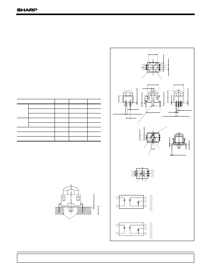
Outline Dimensions
(Unit : mm)
5.5
±
0.1
*
*
5
±
0
2
±
1
2
±
0
2
2
*8.35
±
0.5
φ
6
±
01
φ
6
±
01
X′
Y
Y′
X
4
*
*
*2.54
2
+
0
0
7
6
7
2-2
2-0.65
+
2C.
0.3
2-0.4
2-0.2
+
0.2
2-0.2
+
0.2
2-0.6
+
0.3
2-0.2
+
0.2
3-0.4
φ
08
φ
0
φ
1
±
05
3
±
0
1
±
0
2
φ
15
±
0075
3
+
0
0
5-0.15
+
0.2
0.1
1
5
3
2
4
5
1
4
3
2
1
2
3
4
5
Anode (Light emitting diode)
Anode (Common)
Cathode (Photodiode 1)
Cathode (Photodiode 2)
Cathode (Light emitting diode)
Internal configuration
X-X' section
Internal connection diagram (
GP2TD04
)
5
1
4
3
2
1
2
3
4
5
Anode (Light emitting diode)
Cathode (Photodiode 1, 2)
Anode (Photodiode 1)
Anode (Photodiode 2)
Cathode (Light emitting diode)
Internal connection diagram(
GP2TD03
)
PD window (2-divided PD)
GL window
* Dimension shall be lead root portion
C
Unspecified tolerance :
±
0.2mm
1
2
3
4
5
Symbol
I
F
V
R
P
D (IN)
Rating
50
6
75
Unit
mA
V
mW
Input
Output
75
mW
C
C
C
10 to
+
70
40 to
+
85
260
Storage temperature
Soldering temperature
*1 For 5s below the tie bar cut part (0.45mm from the face A).
Operating temperature
20
V
Reverse voltage
Power dissipation
V
R
P
D(OUT)
T
opr
T
stg
T
sol
(Ta
=
25C)
*1
1. LD players
2. DVD players
I
Features
I
Applications
Tilt Sensor for Optical Disk
1. With built-in lens
2. Compact
3. Linear output current can be obtained in conformance with
tilt angle.
Notice
In the absence of confirmation by device specification sheets, SHARP takes no responsibility for any defects that may occur in equipment using any SHARP
devices shown in catalogs, data books, etc. Contact SHARP in order to obtain the latest device specification sheets before using any SHARP device.
Internet address for Electronic Components Group http://www.sharp.co.jp/ecg/
Internet
Soldering area
0
A
相關(guān)PDF資料 |
PDF描述 |
|---|---|
| GP2U04 | |
| GP2W0004XP | Optoelectronic |
| GP2W0114YPS | INFRARED DATA COMMUNICATION DEVICE |
| GP2W0116YPS | INFRARED DATA COMMUNICATION DEVICE |
| GP2W0118YPS | INFRARED DATA COMMUNICATION DEVICE |
相關(guān)代理商/技術(shù)參數(shù) |
參數(shù)描述 |
|---|---|
| GP2U04 | 制造商:未知廠家 制造商全稱:未知廠家 功能描述: |
| GP2U05 | 制造商:SHARP 制造商全稱:Sharp Electrionic Components 功能描述:Particulate Detectable High Sensitivity Type Dust Sensor |
| GP2U06 | 制造商:Sharp Microelectronics 功能描述:Air Quality Sensor Compact Dust Sensor 5V 10mA 0.5V 0.5V/0.1mg/m^3 |
| GP2U06J0000F | 制造商:SHARP 功能描述:DUST SENSOR |
| GP2W0001 | 制造商:SHARP 制造商全稱:Sharp Electrionic Components 功能描述:Low Power Infrared Transceiver |
發(fā)布緊急采購,3分鐘左右您將得到回復(fù)。