- 您現(xiàn)在的位置:買賣IC網(wǎng) > PDF目錄385310 > GRM319R71A105KC01 (Electronic Theatre Controls, Inc.) High Dielectric Constant Type 6.3/16/25/50V PDF資料下載
參數(shù)資料
| 型號: | GRM319R71A105KC01 |
| 廠商: | Electronic Theatre Controls, Inc. |
| 英文描述: | High Dielectric Constant Type 6.3/16/25/50V |
| 中文描述: | 高介電常數(shù)型6.3/16/25/50V |
| 文件頁數(shù): | 6/13頁 |
| 文件大小: | 188K |
| 代理商: | GRM319R71A105KC01 |
The measured and observed characteristics should satisfy the
specifications in the following table
More than 10,000M
or 500
F (Whichever is smaller)
Within
T
2.5% or
T
0.25pF
(Whichever is larger)
30pF and over : Q
U
1000
30pF and below :
Q
U
400
W
20C
C : Nominal Capacitance (pF)
Resistance
to
Soldering
Heat
14
Preheat the capacitor at 120 to 150
D
for 1 minute.
Immerse the capacitor in an eutectic solder solution at 270
for 10
T
0.5 seconds. Set at room temperature for 24
T
2 hours
(temperature compensating tyoe) or 48
T
4 hours (high dielectric
constant type), then measure.
#
Initial measurement for high dielectric constant type
Perform a heat treatment at 150
W
0/
Y
10
D
for one hour and
then set at room temperature for 48
T
4 hours.
Perform the initial measurement.
#
Preheating for GRM32/43/55
B1, B3, R1, R6, R7
: Within
T
7.5%
F1, F5, E4 : Within
T
20%
[B1, B3, R1, R6, R7, E4]
W.V. : 25Vmin. : 0.025max.
W.V. : 16/10V : 0.035max.
W.V. : 6.3V/4V
: 0.05max. (C
F
3.3μF)
: 0.1max. (C
U
3.3μF)
[F1, F5]
W.V. : 25Vmin.
: 0.05max. (C
F
0.1μF)
: 0.09max. (C
U
0.1μF)
W.V. : 16V/10V : 0.125max.
W.V. : 6.3V : 0.15max.
Appearance
I.R.
No defects
Dielectric
Strength
Capacitance
Change
Q/D.F.
75% of the terminations are to be soldered evenly and
continuously
Solderability of
Termination
13
Immerse the capacitor in a solution of ethanol (JIS-K-8101) and
rosin (JIS-K-5902) (25% rosin in weight propotion) .
Preheat at 80 to 120
D
for 10 to 30 seconds.
After preheating, immerse in an eutectic solder solution for
2
T
0.5 seconds at 230
T
5
D
.
No defects or abnormalities
Step
1
2
100
D
to 120
D
170
D
to 200
D
1 min.
1 min.
Temperature
Time
Continued on the following page.
30pF and over : Q
U
1000
30pF and below :
Q
U
400
W
20C
C : Nominal Capacitance (pF)
[B1, B3, R1, R6, R7, E4]
W.V. : 25Vmin. : 0.025max.
W.V. : 16/10V : 0.035max.
W.V. : 6.3V/4V
: 0.05max. (C
F
3.3μF)
: 0.1max. (C
U
3.3μF)
[F1, F5]
W.V. : 25Vmin.
: 0.05max. (C
F
0.1μF)
: 0.09max. (C
U
0.1μF)
W.V. : 16V/10V : 0.125max.
W.V. : 6.3V : 0.15max.
No defects or abnormalities
Within the specified tolerance
Vibration
Resistance
Deflection
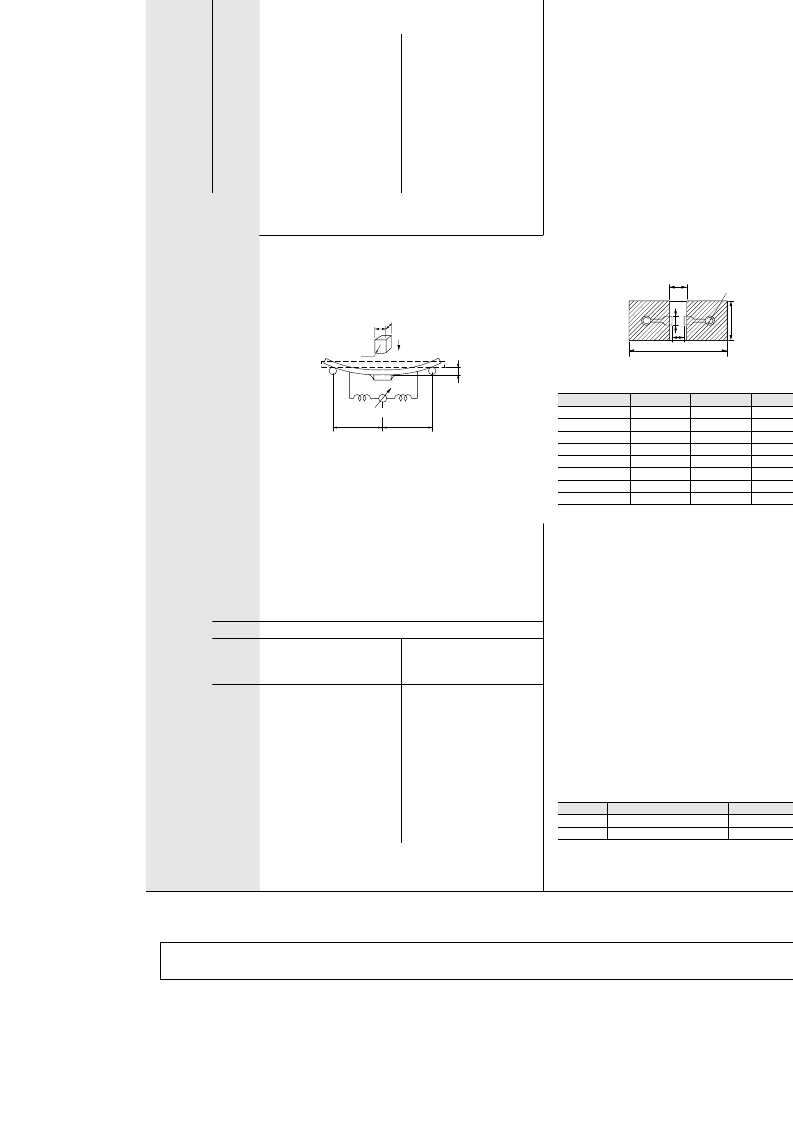
11
12
Solder the capacitor on the test jig (glass epoxy board) shown
in Fig. 2a using an eutectic solder. Then apply a force in the
direction shown in Fig. 3a for 5
T
1sec. The soldering should be
done either with an iron or using the reflow method and should
be conducted with care so that the soldering is uniform and free
of defects such as heat shock.
Solder the capacitor on the test jig (glass epoxy board) in the
same manner and under the same conditions as (10).
The capacitor should be subjected to a simple harmonic motion
having a total amplitude of 1.5mm, the frequency being varied
uniformly between the approximate limits of 10 and 55Hz. The
frequency range, from 10 to 55Hz and return to 10Hz, should
be traversed in approximately 1 minute. This motion should be
applied for a period of 2 hours in each 3 mutually perpendicular
directions (total of 6 hours).
Appearance
Capacitance
Q/D.F.
b
100
Fig. 2a
GR
p
03
GR
p
15
GRM18
GRM21
GRM31
GRM32
GRM43
GRM55
4.5
0.3
0.4
1.0
1.2
2.2
2.2
3.5
¤
0.9
1.5
3.0
4.0
5.0
5.0
7.0
8.0
a
c
4
Capacitance meter
45
Flexure :
V
1
20
50
R230
Pressurizing
speed : 1.0mm/sec.
Pressurize
45
Fig. 3a
No crack or marked defect should occur
Type
a
b
c
0.3
0.5
1.2
1.65
2.0
2.9
3.7
5.6
(in mm)
t : 1.6mm (GR
p
03/15 : t : 0.8mm)
!
Note
This catalog has only typical specifications because there is no space for detailed specifications. Therefore, please approve our product specification or transact the approval sheet for product specification
before ordering. Especially, please read rating and
!
CAUTION (for storage and operating, rating, soldering and mounting, handling) in them to prevent smoking and/or burning, etc.
You are able to read a detailed specification in the website (http://search.murata.co.jp/) before to require our product specification or to transact the approval sheet for product specification.
相關(guān)PDF資料 |
PDF描述 |
|---|---|
| GRM319R71A225KA01 | High Dielectric Constant Type 6.3/16/25/50V |
| GRM319R71C105KC11 | High Dielectric Constant Type 6.3/16/25/50V |
| GRM319R71E684KC01 | High Dielectric Constant Type 6.3/16/25/50V |
| GRM319R71H334KA01 | High Dielectric Constant Type 6.3/16/25/50V |
| GRM31C | High Dielectric Constant Type 6.3/16/25/50V |
相關(guān)代理商/技術(shù)參數(shù) |
參數(shù)描述 |
|---|---|
| GRM319R71A105KC01D | 功能描述:多層陶瓷電容器MLCC - SMD/SMT 1206 1.0uF 10volt X7R +/-10% RoHS:否 制造商:American Technical Ceramics (ATC) 電容:10 pF 容差:1 % 電壓額定值:250 V 溫度系數(shù)/代碼:C0G (NP0) 外殼代碼 - in:0505 外殼代碼 - mm:1414 工作溫度范圍:- 55 C to + 125 C 產(chǎn)品:Low ESR MLCCs 封裝:Reel |
| GRM319R71A105KC01J | 功能描述:多層陶瓷電容器MLCC - SMD/SMT 1206 1.0uF 10volt X7R +/-10% RoHS:否 制造商:American Technical Ceramics (ATC) 電容:10 pF 容差:1 % 電壓額定值:250 V 溫度系數(shù)/代碼:C0G (NP0) 外殼代碼 - in:0505 外殼代碼 - mm:1414 工作溫度范圍:- 55 C to + 125 C 產(chǎn)品:Low ESR MLCCs 封裝:Reel |
| GRM319R71A105MC01D | 功能描述:多層陶瓷電容器MLCC - SMD/SMT 1206 1.0uF 10volt X7R +/-20% RoHS:否 制造商:American Technical Ceramics (ATC) 電容:10 pF 容差:1 % 電壓額定值:250 V 溫度系數(shù)/代碼:C0G (NP0) 外殼代碼 - in:0505 外殼代碼 - mm:1414 工作溫度范圍:- 55 C to + 125 C 產(chǎn)品:Low ESR MLCCs 封裝:Reel |
| GRM319R71A225KA01 | 制造商:未知廠家 制造商全稱:未知廠家 功能描述:High Dielectric Constant Type 6.3/16/25/50V |
| GRM319R71A824KC01D | 功能描述:多層陶瓷電容器MLCC - SMD/SMT 0.82uF 10Volts X7R 10% RoHS:否 制造商:American Technical Ceramics (ATC) 電容:10 pF 容差:1 % 電壓額定值:250 V 溫度系數(shù)/代碼:C0G (NP0) 外殼代碼 - in:0505 外殼代碼 - mm:1414 工作溫度范圍:- 55 C to + 125 C 產(chǎn)品:Low ESR MLCCs 封裝:Reel |
發(fā)布緊急采購,3分鐘左右您將得到回復(fù)。