- 您現(xiàn)在的位置:買賣IC網(wǎng) > PDF目錄383014 > GS4882-CDA (Electronic Theatre Controls, Inc.) Video Sync Separators with 50% Sync Slicing PDF資料下載
參數(shù)資料
| 型號: | GS4882-CDA |
| 廠商: | Electronic Theatre Controls, Inc. |
| 英文描述: | Video Sync Separators with 50% Sync Slicing |
| 中文描述: | 視頻同步分離器50%同步分層 |
| 文件頁數(shù): | 5/7頁 |
| 文件大?。?/td> | 85K |
| 代理商: | GS4882-CDA |

5 of 7
521 - 61 - 01
OOUTPUT
(Pin 7)
V
(Pin 8)
R
(Pin 6)
VE OUTPUT
(PIN 3)
DETECTOR
SC(Pin 1)
HORIZONTAL
CLEN
VERTICAL
IINTEGRATED
HOLD
ORDER
2
ND
F ORDER
SIGNAL
DETECT
MUTE
WINDOWING
CIRCUIT
FAULT
HANDLING
CLAMP
WINDOW
+
+
-
-
BAOUTPUT
(Pin 5)
VOLTAGE
REGULATOR
TIMING
CURRENTS
-
+
CLK Q
D
Q
G
Q
Q
D
CLK
D
Q
Q
227k
0.1
μ
V
HC
V
SC
V
SC
+
-
R
50%
POINT
R
2
ND
BESSEL
INPUT
(Pin 2)
NO SYNC
BPEN
0.1
μ
Assuming that the sync separator is in steady state operation
with a valid input signal, all outputs will be enabled. Removal
of the input signal, or a significant change in the input signal
frequency, will cause an internal probation timer to be triggered.
While on probation, the sync separator outputs remain
enabled and separated sync is still produced. If a valid input
signal is not returned to the system before the probation time
expires (typically 2.5 ms), all outputs will be muted to logic
high state. Should a valid signal return during the probation
period, and eight lines be received before the probation time
expires, device outputs will remain enabled. Once device
outputs are muted, the device must receive 8 valid lines of
video at the correct horizontal frequency before the outputs
are re-enabled.
SIGNAL DETECT AND OUTPUT MUTE
Internal to the GS4882 and GS4982 is a robust video signal
detection circuit. This circuit provides a reliable control signal
that will enable the sync separator outputs only when a valid
video signal is present. When the input signal is not valid, the
outputs are muted and stay in a logic high state.
The GS4882 and GS4982 differentiate between valid and in-
valid input signals by feeding the horizontal sync information
into a frequency to voltage converter. The horizontal scan rate
of the input signal is then compared to an expected input
signal horizontal scan rate. With R
SET
=227 k
, the sync
separator will typically define a valid input signal as one with
a horizontal frequency of 15.7 ± 4 kHz.
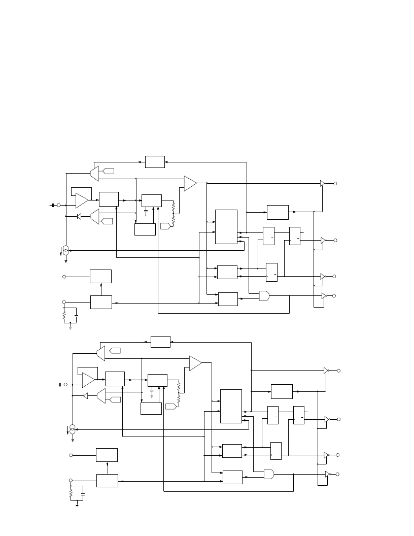
Fig. 6 GS4882 Block Diagram
OOUTPUT
(Pin 7)
CC
(V
R
(Pin 6)
VE OUTPUT
(PIN 3)
DETECTOR
HO(Pin 1)
HORIZONTAL
VERTICAL
SIGNAL
DETECT
MUTE
+
+
-
-
BAOUTPUT
(Pin 5)
VOLTAGE
REGULATOR
TIMING
CURRENTS
-
-
+
+
CLK Q
D
Q
G
Q
Q
D
CLK
D
Q
Q
227k
0.1
μ
R
50%
POINT
R
2
ND
ORDER
BESSEL
FILTER
INPUT
(Pin 2)
NO SYNC
0.1
μ
WINDOWING
CIRCUIT
CLAMP
WINDOW
INTEGRATED
HOLD
FAULT
HANDLING
V
SC
V
HC
V
SC
CLEN
BPEN
Fig. 7 GS4982 Block Diagram
相關(guān)PDF資料 |
PDF描述 |
|---|---|
| GS4882-CKA | Video Sync Separators with 50% Sync Slicing |
| GS4882-CKAE3 | Video Sync Separators with 50% Sync Slicing |
| GS4882-CTA | Video Sync Separators with 50% Sync Slicing |
| GS4982 | Video Sync Separators with 50% Sync Slicing |
| GS4982-CKAE3 | Video Sync Separators with 50% Sync Slicing |
相關(guān)代理商/技術(shù)參數(shù) |
參數(shù)描述 |
|---|---|
| GS4882CKA | 制造商:Gennum Corporation 功能描述: |
| GS4882-CKA | 制造商:Gennum Corporation 功能描述: |
| GS4882-CKAE3 | 制造商:Semtech Corporation 功能描述:Video Sync Separator 8-Pin SOIC 制造商:Gennum Corporation 功能描述: 制造商:Semtech Corporation 功能描述:Sync Separators |
| GS4882-CTA | 制造商:GENNUM 制造商全稱:GENNUM 功能描述:Video Sync Separators with 50% Sync Slicing |
| GS4882-CTAE3 | 制造商:Semtech Corporation 功能描述:TAPE & REEL Sync Separators |
發(fā)布緊急采購,3分鐘左右您將得到回復(fù)。