- 您現(xiàn)在的位置:買賣IC網(wǎng) > PDF目錄383014 > GS7000-CTT (Electronic Theatre Controls, Inc.) Serial Digital Video Transceiver PDF資料下載
參數(shù)資料
| 型號: | GS7000-CTT |
| 廠商: | Electronic Theatre Controls, Inc. |
| 英文描述: | Serial Digital Video Transceiver |
| 中文描述: | 串行數(shù)字視頻收發(fā)器 |
| 文件頁數(shù): | 3/14頁 |
| 文件大小: | 172K |
| 代理商: | GS7000-CTT |
522 - 06 - 02
3
G
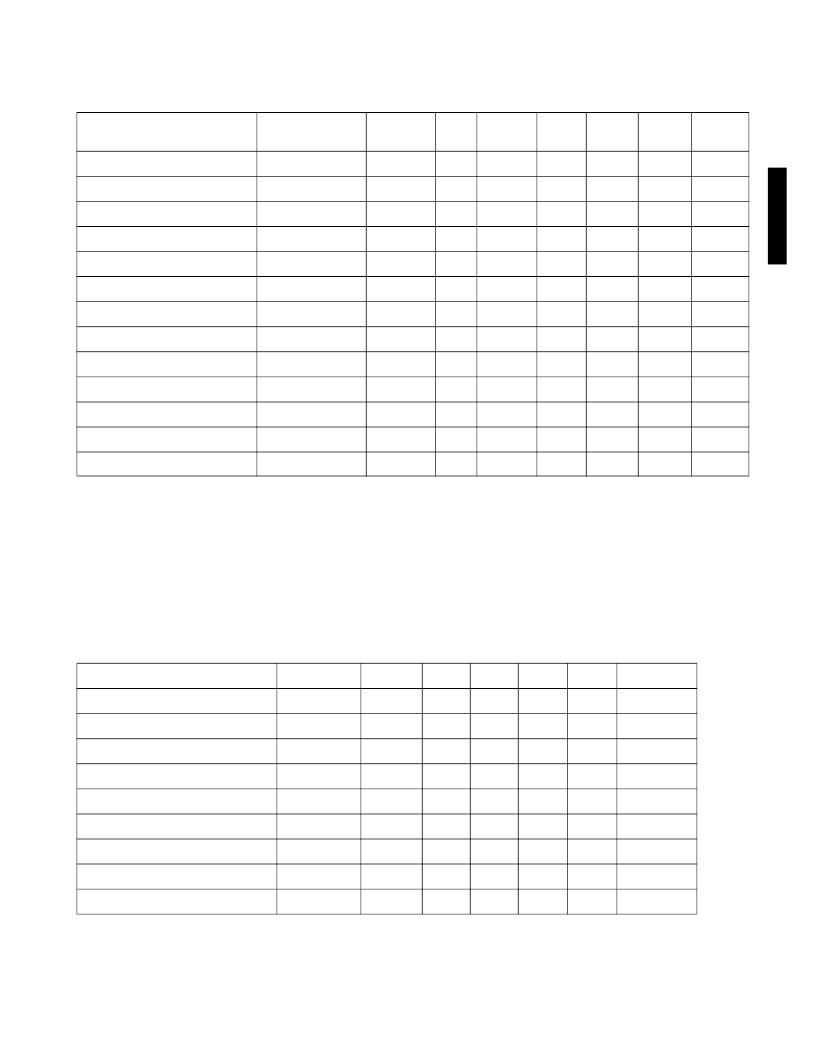
AC ELECTRICAL CHARACTERISTICS (Transmitter Mode)
V
= 5V, V
= 0V, T
= 0°C to 85°C, unless otherwise specified in ‘conditions’
Serial Data Rate = 270Mb/s, Parallel Data Rate = 27Mb/s, f
PCLK
= 27MHz
PARAMETER
CONDITIONS
SYMBOL
MIN
TYP
MAX
UNITS
NOTES
TEST
LEVEL
Parallel Data Inputs - rise/fall time
t
R/F_DPI
0.5
10
ns
1
2
Parallel Data Inputs - setup
t
SETUP
4
-
-
ns
8
1
Parallel Data Inputs - hold
t
HOLD
4
-
-
ns
8
1
Parallel Data Inputs - high
V
CC
= 5.25V
V
DPI
2.0
-
V
CC
V
1
Parallel Data Inputs - low
V
CC
= 4.75V
V
DPI
V
EE
-
0.8
V
1
Parallel Clock Input - rise/fall time
t
R/F_PCLK
0.5
-
4
ns
2
Serial Data Output - signal swing
V
CC
= 4.75 - 5.25V
V
DSO
720
800
880
mV p-p
9, 10
1
Serial Data Output - high
V
OH
-
V
CC
- 0.8
-
V
11
2
Serial Data Output - low
V
OL
-
V
CC
- 1.6
-
V
11
2
Serial Data Output - rise/fall time
t
R/F
400
600
1500
ps
1
1
Serial Data Output - jitter
V
CC
= 4.75V
t
J_DSO
-
-
675
ps p-p
12
1
Lock Time
t
LOCK
-
-
250
ms
13
1
Output Return Loss
270MHz
15
-
-
dB
6
NOTES
8. Refer to Figure 26.
9. The outputs are capable of driving a 75
single-ended load, terminated to ground.
10.This value is measured after the resistor network at the SDI outputs shown in Figure 2.
11.Typical PECL values
12.6
σ
additive intrinsic jitter contribution based on pathological input signal
13.This is the lapsed time between valid parallel TRS input to valid serial output
TEST LEVELS
1. 100% tested at 25°C
2. Guaranteed by design
3. Inferred or correlated value
4. Evaluated using test setup Figure 1a.
5. Evaluated using test setup Figure 1b.
6. Evaluated using test setup Figure 1c.
DC ELECTRICAL CHARACTERISTICS
V
= 5V, V
= 0V, T
= 0°C to 85°C, unless otherwise specified.
Serial Data Rate = 270Mb/s, Parallel Data Rate = 27Mb/s, f
PCLK
= 27MHz
PARAMETER
CONDITIONS
SYMBOL
MIN
TYP
MAX
UNITS
TEST LEVEL
Positive Supply Voltage
V
CC
+ 4.75
+ 5.00
+ 5.25
V
Supply Current - Receive Mode
V
CC
= 5.25V
I
CC
-
150
-
mA
1
Supply Current - Transmit Mode
V
CC
= 5.25V
I
CC
-
130
-
mA
1
Power Consumption - Receive Mode
V
CC
= 5.25V
P
D
-
750
-
mW
3
Power Consumption - Transmit Mode
V
CC
= 5.25V
P
D
-
650
-
mW
3
Logic Inputs - Low
V
CC
= 5.25V
V
IL
V
EE
-
0.8
V
2
Logic Inputs - High
V
CC
= 4.75V
V
IH
2.0
-
V
CC
V
2
Logic Outputs - Low
V
CC
= 5.25V
V
OL
V
EE
-
0.5
V
2
Logic Outputs - High
V
CC
= 4.75V
V
OH
2.4
-
V
CC
V
2
相關(guān)PDF資料 |
PDF描述 |
|---|---|
| GS7005 | Complete Serial Digital Video Receiver |
| GS7005-CQT | Complete Serial Digital Video Receiver |
| GS7005-CTT | Complete Serial Digital Video Receiver |
| GS7025 | Serial Digital Receiver |
| GS7025-CQM | Serial Digital Receiver |
相關(guān)代理商/技術(shù)參數(shù) |
參數(shù)描述 |
|---|---|
| GS7005 | 制造商:未知廠家 制造商全稱:未知廠家 功能描述:Complete Serial Digital Video Receiver |
| GS7005CQT | 制造商:Gennum Corporation 功能描述: |
| GS7005-CQT | 制造商:未知廠家 制造商全稱:未知廠家 功能描述:Complete Serial Digital Video Receiver |
| GS7005-CTT | 制造商:GENNUM 制造商全稱:GENNUM 功能描述:Complete Serial Digital Video Receiver |
| GS702 | 制造商:未知廠家 制造商全稱:未知廠家 功能描述:Flexible Remote Control (FRC) Technology ? Transmitter |
發(fā)布緊急采購,3分鐘左右您將得到回復(fù)。