- 您現(xiàn)在的位置:買賣IC網(wǎng) > PDF目錄383055 > GS9025ACQM (Electronic Theatre Controls, Inc.) Serial Digital Receiver PDF資料下載
參數(shù)資料
| 型號(hào): | GS9025ACQM |
| 廠商: | Electronic Theatre Controls, Inc. |
| 英文描述: | Serial Digital Receiver |
| 中文描述: | 串行數(shù)字接收機(jī) |
| 文件頁(yè)數(shù): | 12/18頁(yè) |
| 文件大小: | 192K |
| 代理商: | GS9025ACQM |
第1頁(yè)第2頁(yè)第3頁(yè)第4頁(yè)第5頁(yè)第6頁(yè)第7頁(yè)第8頁(yè)第9頁(yè)第10頁(yè)第11頁(yè)當(dāng)前第12頁(yè)第13頁(yè)第14頁(yè)第15頁(yè)第16頁(yè)第17頁(yè)第18頁(yè)
GENNUM CORPORATION
522 - 75 - 00
12
G
The average sweep time, t
swp
, is determined by the loop
filter component, C
LF1
, and the charge pump current,
Ι
CP
:
The nominal sweep time is approximately 121μs when
C
LF1
= 15nF and
Ι
CP
= 165μA (R
VCO
= 365
).
An internal system clock determines t
sys
(see section 3-1,
Logic Circuit)
3-1. Logic Circuit
The GS9025A is controlled by a finite state logic circuit
which is clocked by an asynchronous system clock. That is,
the system clock is completely independent of the incoming
data rate. The system clock runs at low frequencies, relative
to the incoming data rate, and thus reduces interference to
the PLL.The period of the system clock is set by the COSC
capacitor and is:
The recommended value for t
sys
is 450μs (C
OSC
= 4.7nF)
4. AUTO/MANUAL DATA RATE SELECT
The GS9025A can operate in either auto or manual data
rate select mode. The mode of operation is selected by a
single input pin (AUTO/MAN).
4-1. Auto Mode (AUTO/MAN = 1)
In auto mode, the GS9025A uses a 3-bit counter to
automatically cycle through five (SMPTE=1) or three
(SMPTE=0) different divider moduli as it attempts to acquire
lock. In this mode, the SS[2:0] pins are outputs and indicate
the current value of the divider moduli according Table 2.
NOTE: For SMPTE = 0 and divider moduli of 2 and 4, the
PLL can correctly lock for two values of SS[2:0].
4-2. Manual Mode (AUTO/MAN = 0)
In manual mode, the GS9025A divider moduli is fixed. In
this mode, the SS[2:0] pins are inputs and set the divider
moduli according to Table 3.
5. LOCKING
The GS9025A indicates lock when three conditions are
satisfied:
1. Input data is detected.
2. The incoming data signal and the PLL clock are phase
locked.
3. The system is not locked to a harmonic.
t
SWP
4C
3
I
CP
----------------
=
t
sys
9.6
10
4
C
OSC
onds
sec
[
]
×
×
=
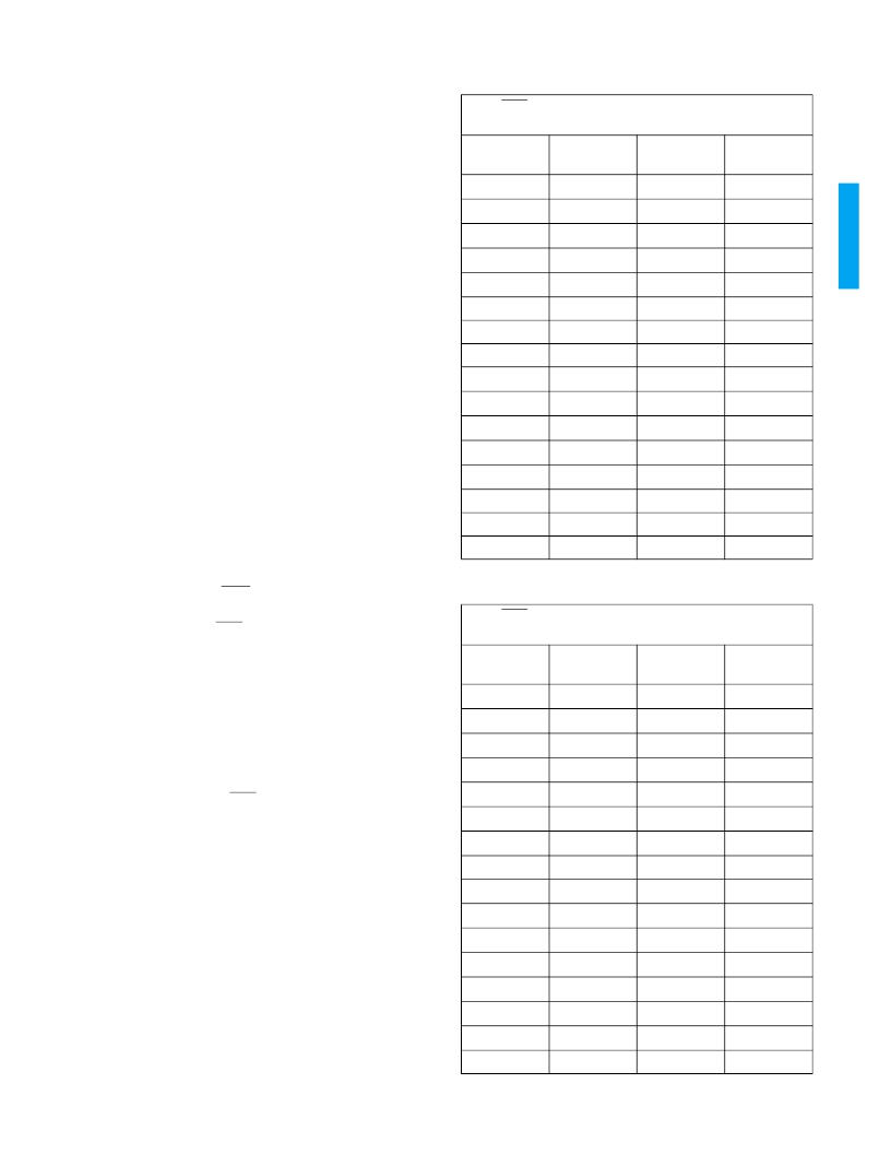
TABLE 2.
AUTO/MAN = 1 (AUTO MODE)
H
,
L
= VCO centre frequency as per Figure 19.
SMPTE
SS[2:0]
DIVIDER
MODULI
PLL CLOCK
1
000
4
H
/4
1
001
2
L
/2
1
010
2
H
/2
1
011
1
L
1
100
1
H
1
101
-
-
1
110
-
-
1
111
-
-
0
000
4
H
/4
0
001
4
H
/4
0
010
2
H
/2
0
011
2
H
/2
0
100
1
H
0
101
-
-
0
110
-
-
0
111
-
-
TABLE 3.
AUTO/MAN = 1 (MANUAL MODE)
H
,
L
= VCO centre frequency as per Figure 19.
SMPTE
SS[2:0]
DIVIDER
MODULI
PLL CLOCK
1
000
4
H
/4
1
001
2
L
/2
1
010
2
H
/2
1
011
1
L
1
100
1
H
1
101
8
L
/8
1
110
8
H
/8
1
111
-
-
0
000
4
H
/4
0
001
4
H
/4
0
010
2
H
/2
0
011
2
H
/2
0
100
1
H
0
101
1
H
0
110
8
H
/8
0
111
-
-
相關(guān)PDF資料 |
PDF描述 |
|---|---|
| GS9025ACTM | Serial Digital Receiver |
| GS9028 | Cable Driver with Two Adjustable Outputs |
| GS9028-CKA | Cable Driver with Two Adjustable Outputs |
| GS9028-CTA | Cable Driver with Two Adjustable Outputs |
| GS9029 | GENLINX ⑩ GS9029 Quad Output Serial Digital Video Cable Driver |
相關(guān)代理商/技術(shù)參數(shù) |
參數(shù)描述 |
|---|---|
| GS9025ACQME3 | 制造商:Semtech Corporation 功能描述:Cable Equalization 44-Pin MQFP Tray 制造商:Semtech Corporation 功能描述:GS9025 Series 540 Mb/s Cable Equalization Serial Digital Receiver - MQFP-44 制造商:Semtech Corporation 功能描述:Receiver |
| GS9025ACTM | 制造商:GENNUM 制造商全稱:GENNUM 功能描述:Serial Digital Receiver |
| GS9025ACTME3 | 制造商:Semtech Corporation 功能描述:Receiver |
| GS9028 | 制造商:GENNUM 制造商全稱:GENNUM 功能描述:Cable Driver with Two Adjustable Outputs |
| GS9028_04 | 制造商:GENNUM 制造商全稱:GENNUM 功能描述:Cable Driver with Two Adjustable Outputs |
發(fā)布緊急采購(gòu),3分鐘左右您將得到回復(fù)。