- 您現(xiàn)在的位置:買賣IC網(wǎng) > PDF目錄69002 > GT5-2022/F2.7-3.5PCF RECTANGULAR CONNECTOR PDF資料下載
參數(shù)資料
| 型號: | GT5-2022/F2.7-3.5PCF |
| 元件分類: | 矩形連接器 |
| 英文描述: | RECTANGULAR CONNECTOR |
| 文件頁數(shù): | 2/22頁 |
| 文件大?。?/td> | 851K |
| 代理商: | GT5-2022/F2.7-3.5PCF |

CAV NO
14.8
10.9
2.8
30
25
18.8
13.4
15.8
22.4
14.15
4
18.8
27.4
7.7
7
21.3
5.45
36
GT5 Series
GT
1
GT
5
GT
13
GT
16
PO5G
GT
11
GT
14
GT
17
GT
19N
GT
2
GT
3
GT
6W
GT
7
GT
10
GT
12
GT
18W
GT
15
GT
8
GT
9
Coaxial
cable
connection
of
Antennas,
Sensors,
and
Communication
T
runk
Lines
22.4
Panel
2-
For inner conductor
For outer conductor
41.4
GT5-2S-HU
GT5-2P/S-R
14.05
0.3
2-R0.7
2-R3.25
19.2
22.4
Board
8.2
3.6
14.05
0.3
2-R0.7
2-R3.25
Board
19.2
20.2
22
1.5
3.6
2-R0.7 14.05
0.3
R3.25
Board
R2.3
20.2
19.2
8.2
11.8
14.05
0.3
2-R3.25
3
2-R0.7
20.2
19.2
3
Figure q
Figure w
Figure e
Figure r
GT5-2P-DS (D)
Recommended Panel Cut-out
GT5-2P-DS (A)
GT5-2P-DS (B)
GT5-2P-DS (C)
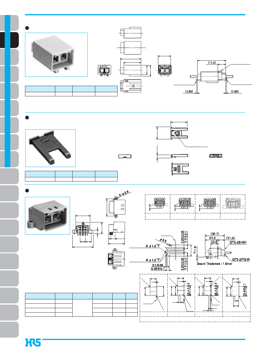
Housing
Retainer – 2 position (Used with GT5-2S-HU, GT5-2PP-HU,
and GT5N-2PP-HU)
Housings
GT5N-2PP-HU
755-0055-8
Part Number
CL No.
Color
Note 1:Terminal extraction tool: GT-PO(A)
Note 2: Used with separate retainer (GT5-2P/S-R).
Light gray
Material
PBT
BDiagram of Mated Connector in Use
GT5-2P/S-R
755-0046-7
Part Number
CL No.
Color
Dark gray
Material
PBT
GT5-2P-DS
GT5-2P-DS(A)
GT5-2P-DS(B)
GT5-2P-DS(C)
755-0043-9
755-0061-0
755-0062-3
755-0101-3
Figure q
Figure w
Figure e
Figure r
D2
A2
B2
C2
Part Number
CL No.
Color
Key polarizing
code
USCAR-19
Coding
Note: Use JIS B 1115 and 1122 class 4, nominal diameter 3, length 6 screws
(for a board thickness of 1.6 mm) for the mounting screws.
Coding D2 at USCAR-19 is GT5-2P-DS.
Light Gray
Brown
Green
Blue
Material
PBT
BRecommended Board Mounting
Pattern
BMounted and fully mated
connector assemblies
BKeying Configurations
The product information in this catalog is for reference only. Please request the Engineering Drawing for the most current and accurate design information.
All non-RoHS products have been discontinued, or will be discontinued soon. Please check the products status on the Hirose website RoHS search at www.hirose-connectors.com, or contact your Hirose sales representative.
相關PDF資料 |
PDF描述 |
|---|---|
| GT5-2022/F2.7-3.5SCF | RECTANGULAR CONNECTOR |
| GT5-2022/F3.3-3.8PCF | RECTANGULAR CONNECTOR |
| GT5-2022/F3.3-3.8SCF | RECTANGULAR CONNECTOR |
| GT5-2022/F3.3-5PCF | RECTANGULAR CONNECTOR |
| GT5-2022/F3.3-5SCF | RECTANGULAR CONNECTOR |
相關代理商/技術參數(shù) |
參數(shù)描述 |
|---|---|
| GT521A10L | 制造商: 功能描述: 制造商:undefined 功能描述: |
| GT521A16L | 制造商: 功能描述: 制造商:undefined 功能描述: |
| GT5-2428/1.1-2.2SCF | 功能描述:汽車連接器 FEMALE TERMINAL 24-28 AWG RoHS:否 制造商:Amphenol SINE Systems 產品:Contacts 系列:ATP 位置數(shù)量: 型式:Female 安裝風格: 端接類型: 觸點電鍍:Nickel |
| GT5-2428/1.6-2.5SCF | 功能描述:汽車連接器 HARNESS TOOL RoHS:否 制造商:Amphenol SINE Systems 產品:Contacts 系列:ATP 位置數(shù)量: 型式:Female 安裝風格: 端接類型: 觸點電鍍:Nickel |
| GT5-2428/1.6-2.5SCF(70 | 制造商:Hirose 功能描述:755-0078-3-70 REEL |
發(fā)布緊急采購,3分鐘左右您將得到回復。