- 您現(xiàn)在的位置:買賣IC網(wǎng) > PDF目錄371775 > HC55171CM (INTERSIL CORP) 5 REN Ringing SLIC for ISDN Modem/TA and WLL PDF資料下載
參數(shù)資料
| 型號: | HC55171CM |
| 廠商: | INTERSIL CORP |
| 元件分類: | 模擬傳輸電路 |
| 英文描述: | 5 REN Ringing SLIC for ISDN Modem/TA and WLL |
| 中文描述: | TELECOM-SLIC, PQCC28 |
| 封裝: | PLASTIC, LCC-28 |
| 文件頁數(shù): | 6/18頁 |
| 文件大?。?/td> | 153K |
| 代理商: | HC55171CM |

67
Circuit Operation and Design Information
Introduction
The HC55171 is a high voltage Subscriber Line Interface Cir-
cuit (SLIC) specifically designed for through SLIC ringing
applications. Through SLIC ringing applications are broadly
defined as any application that requires ringing capability but
does not have the standard wired central office interface. The
most common implementation of the ringing SLIC is in the
analog pots port. The analog pots port provides the ringing
function as well as interface compatibility with answering and
fax machines.
Subscriber Line Interface Basics
The basic SLIC provides DC loop current to power the handset,
supports full duplex analog transmission between the handset
and CODEC, matches the impedance of the SLIC to the
impedance of the handset and performs loop supervision func-
tions to detect when the handset is off hook. The ringing SLIC
adds through the SLIC ringing capability to this suite of fea-
tures.The analog interfaces of the SLIC are categorized as the
2-wire interface (high voltage DC, differential AC) and the 4-wire
interface (low voltage DC, single ended AC).
DC Loop Current
The Tip and Ring terminals of the subscriber line circuit are
biased at negative potentials with respect to ground. The Tip
terminal DC potential is slightly negative with respect to
ground, and the ring terminal DC potential is slightly positive
with respect to the battery voltage (resulting in a large nega-
tive voltage). The HC55171 typical Tip DC voltage is -4V and
the typical ring DC voltage is defined as V
BAT
+ 4V. For exam-
ple, when the battery voltage is -24V the ring voltage is -20V.
To clearly comprehend the Tip and Ring interface it is helpful
to understand that the handset and the SLIC constitute a DC
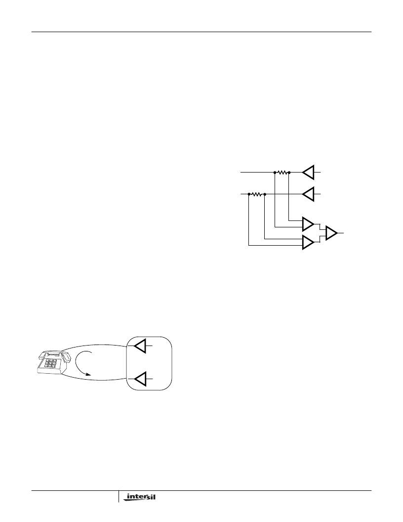
and AC current loop as shown in Figure 1. The loop is often
referred to as the subscriber loop.
When the handset is on hook (idle) the phone is an open cir-
cuit load and the DC loop current is zero. The SLIC can still
provide AC transmission in this condition, which supports
caller id services. The DC resistance of the off hook handset
is typically 400
. Since the Tip DC voltage is more positive
than the ring DC voltage, DC loop current flows from Tip to
Ring when the handset is off hook. The SLIC is designed
with feedback to limit the maximum loop current when the
handset is off hook.
Full Duplex Analog Transmission
Familiarity with the signal paths of the SLIC is critical in
understanding the full duplex transmission capability of the
device. The analog interfaces of the SLIC are categorized as
2-wire interfaces and 4-wire interfaces.
The 2-wire interface of the SLIC consists of the bidirectional
Tip and Ring terminals of the device. A differential transmit-
ter drives AC signals out of the Tip and Ring terminals to the
handset. A differential receiver across Tip and Ring receives
AC signals from the handset. The differential receiver is con-
nected across sense resistors that are in the Tip and Ring
signal paths. The differential transmitter and receiver con-
cept is depicted in Figure 2.
Since the receiver is connected across the transmit signal
path, one may deduce that in addition to receiving signals
from the handset, the receiver will detect part of the transmit
signal. Indeed this does occur and is the reason that all SLIC
circuits require a hybrid balance or echo cancellation func-
tion.
The 4-wire interface of the SLIC consists of the receive
(VRX) and transmit (OUT1) terminals. The 4-wire interfaces
are single ended signal paths. The receiver is a dedicated
input port and the transmitter is a dedicated output port. The
4-wire receive input of the SLIC drives the 2-wire differential
transmitter and the 2-wire differential receiver drives the 4-
wire transmit output.
The complete signal path for voice signals includes two digi-
tal data busses, a CODEC and a SLIC. There is a receive
data bus and transmit data bus, each with an independent 3-
wire serial interface. The CODEC contains a coder and
decoder. The coder converts the SLIC analog transmit out-
put to digital data for the transmit data bus. The receive digi-
tal data bus is converted to analog data and drives the SLIC
receive input.
The CODECs use logarithmic compression schemes to
extend the resolution of the 8-bit data to 14 bits. The
accepted compression schemes are A-law (Intersil CODEC -
CD22357A) and
μ
-law (Intersil CODEC - CD22354A). The
complete signal path from the handset to the CODEC is
shown in Figure 3.
FIGURE 1. SUBSCRIBER LOOP
TIP
RING
SLIC
LOOP
CURRENT
FIGURE 2. DIFFERENTIAL TRANSMIT/RECEIVE CONCEPT
+
-
+
-
+
-
DIFFERENTIAL
TRANSMITTER
DIFFERENTIAL
RECEIVER
-1
HC55171
相關(guān)PDF資料 |
PDF描述 |
|---|---|
| HC55171IM | 5 REN Ringing SLIC for ISDN Modem/TA and WLL |
| HC55185BIM | VoIP Ringing SLIC Family |
| HC55185CIM | VoIP Ringing SLIC Family |
| HC55183ECM | Extended Reach Ringing SLIC Family |
| HC55180DIM | Extended Reach Ringing SLIC Family |
相關(guān)代理商/技術(shù)參數(shù) |
參數(shù)描述 |
|---|---|
| HC55171CM96 | 制造商:Rochester Electronics LLC 功能描述:- Bulk |
| HC55171IB | 制造商:Rochester Electronics LLC 功能描述:- Bulk |
| HC55171IM | 制造商:INTERSIL 制造商全稱:Intersil Corporation 功能描述:5 REN Ringing SLIC for ISDN Modem/TA and WLL |
| HC5517B | 制造商:INTERSIL 制造商全稱:Intersil Corporation 功能描述:Low Cost 3 REN Ringing SLIC for ISDN Modem/TA and WL |
| HC5517B WAF | 制造商:Harris Corporation 功能描述: |
發(fā)布緊急采購,3分鐘左右您將得到回復(fù)。