- 您現(xiàn)在的位置:買賣IC網(wǎng) > PDF目錄371776 > HC5518XEVAL1 (Intersil Corporation) Aluminum Electrolytic Capacitor; Capacitor Type:General Purpose; Voltage Rating:50VDC; Capacitor Dielectric Material:Aluminum Electrolytic; Operating Temperature Range:-40 C to +85 C; Body Diameter:6.3mm; Body Length:5.4mm RoHS Compliant: Yes PDF資料下載
參數(shù)資料
| 型號(hào): | HC5518XEVAL1 |
| 廠商: | Intersil Corporation |
| 英文描述: | Aluminum Electrolytic Capacitor; Capacitor Type:General Purpose; Voltage Rating:50VDC; Capacitor Dielectric Material:Aluminum Electrolytic; Operating Temperature Range:-40 C to +85 C; Body Diameter:6.3mm; Body Length:5.4mm RoHS Compliant: Yes |
| 中文描述: | 大位移振鈴用戶接口家庭 |
| 文件頁數(shù): | 15/17頁 |
| 文件大小: | 168K |
| 代理商: | HC5518XEVAL1 |
4-15
Uncommitted Switch
Overview
The uncommitted switch is a three terminal device designed
for flexibility. The independent logic control input, SWC,
allows switch operation regardless of device operating
mode. The switch is activated by a logic low. The positive
and negative terminals of the device are labeled SW+ and
SW- respectively.
Relay Driver
The uncommitted switch may be used as a relay driver by
connecting SW+ to the relay coil and SW- to ground. The
switch is designed to have a maximum on voltage of 0.6V
with a load current of 45mA.
Since the device provides the ringing waveform, the relay
functions which may be supported include subscriber
disconnect, test access or line interface bypass. An external
snubber diode is not required when using the uncommitted
switch as a relay driver.
Test Load
The switch may be used to connect test loads across Tip
and Ring. The test loads can provide external test
termination for the device. Proper connection of the
uncommitted switch to Tip and Ring is shown below.
The diode in series with the test load blocks current from
flowing through the uncommitted switch when the polarity of
the Tip and Ring terminals are reversed. In addition to the
reverse active state, the polarity of Tip and Ring are reversed
for half of the ringing cycle. With independent logic control
and the blocking diode, the uncommitted switch may be
continuously connected to the Tip and Ring terminals.
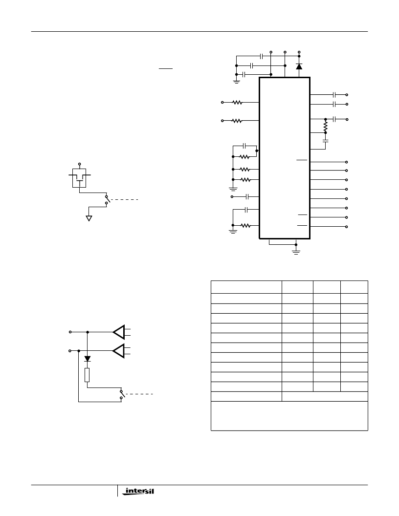
Basic Application Circuit
C
PS1
FIGURE 13. EXTERNAL RELAY SWITCHING
RELAY
SW+
SW-
SWC
+5V
FIGURE 14. TEST LOAD SWITCHING
RING
TIP
TEST
LOAD
SW+
SW-
SWC
TABLE 4. BASIC APPLICATION CIRCUIT COMPONENT LIST
COMPONENT
VALUE
TOL
RATING
U1 - Ringing SLIC
HC55185
N/A
N/A
R
TL
R
RT
R
SH
R
IL
R
S
C
RX
, C
RS
, C
TX
, C
RT
, C
POL
C
DC
, C
FB
C
PS1
C
PS2
, C
PS3
D
1
R
P1
, R
P2
Standard applications will use
≥
49
per side. Protection resistor
values are application dependent and will be determined by
protection requirements.
18.7k
1%
0.1W
23.7k
1%
0.1W
49.9k
1%
0.1W
71.5k
1%
0.1W
66.5k
1%
0.1W
0.47
μ
F
20%
10V
4.7
μ
F
20%
10V
0.1
μ
F
20%
>100V
0.1
μ
F
20%
100V
1N400X type with breakdown > 100V.
Design Parameters
: Ring Trip Threshold = 76mA
PEAK
, Switch
Hook Threshold = 12mA, Loop Current Limit = 24.6mA, Synthesize
Device Impedance = (3*66.5k
)
/400 = 498.8
, with 49.9
protection resistors, impedance across Tip and Ring
terminals = 599
. Transient current limit = 95mA.
FIGURE 15. HC55185 BASIC APPLICATION CIRCUIT
VRX
VRS
TIP
VFB
BGND
AGND
RING
VTX
-IN
SW+
SW-
BSEL
RD
RTD
CDC
ILIM
E0
F2
F1
F0
DET
ALM
HC55185
V
CC
POL
SWC
C
RX
C
RS
C
TX
R
IL
C
FB
R
S
R
SH
C
RT
R
RT
C
POL
C
DC
U
1
R
P1
R
P2
VCC
VBL
VBH
D
1
C
PS3
C
PS2
TL
R
TL
HC55185
相關(guān)PDF資料 |
PDF描述 |
|---|---|
| HC55185FCM | VoIP Ringing SLIC Family |
| HC6094IN | ADSL Analog Front End Chip |
| HC6094 | DRAM Memory IC; Memory Type:NMOS DRAM; Access Time, Tacc:200ns; Package/Case:16-DIP; Memory Configuration:4K x 1; Mounting Type:Through Hole |
| HC6616JCHZC | x8 ROM (Mask Programmable) |
| HC6616JCHZT | x8 ROM (Mask Programmable) |
相關(guān)代理商/技術(shù)參數(shù) |
參數(shù)描述 |
|---|---|
| HC5519 | 制造商:HARRIS 制造商全稱:HARRIS 功能描述:SLIC Subscriber Line Interface Circuit |
| HC5519 WAF | 制造商:Harris Corporation 功能描述: |
| HC5519CQ | 制造商:HARRIS 制造商全稱:HARRIS 功能描述:SLIC Subscriber Line Interface Circuit |
| HC5520 | 制造商:HARRIS 制造商全稱:HARRIS 功能描述:CO/PABX Polarity Reversal Subscriber Line Interface Circuit |
| HC5520CM | 制造商:HARRIS 制造商全稱:HARRIS 功能描述:CO/PABX Polarity Reversal Subscriber Line Interface Circuit |
發(fā)布緊急采購,3分鐘左右您將得到回復(fù)。