- 您現(xiàn)在的位置:買賣IC網(wǎng) > PDF目錄384398 > HE84760 (King Billion Electronics Co., Ltd.) 8-bit Micro-controller PDF資料下載
參數(shù)資料
| 型號: | HE84760 |
| 廠商: | King Billion Electronics Co., Ltd. |
| 英文描述: | 8-bit Micro-controller |
| 中文描述: | 8位微控制器 |
| 文件頁數(shù): | 18/31頁 |
| 文件大小: | 457K |
| 代理商: | HE84760 |
第1頁第2頁第3頁第4頁第5頁第6頁第7頁第8頁第9頁第10頁第11頁第12頁第13頁第14頁第15頁第16頁第17頁當(dāng)前第18頁第19頁第20頁第21頁第22頁第23頁第24頁第25頁第26頁第27頁第28頁第29頁第30頁第31頁
King Billion Electronics Co., Ltd
駿
億
電
子
股
份
有
限
公
司
HE84760
HE80000 SERIES
10.
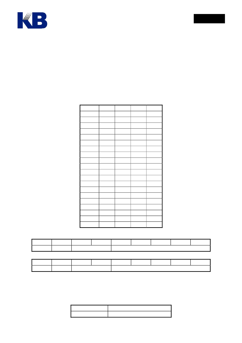
Key Scan Circuit
August 15, 2003
This specification is subject to change without notice. Please contact sales person for the latest version before use.
Page 18 of 31
V1.2
The built-in 4x20 hardware keyboard scan circuit helps to reduce the pin counts where application
requires large key matrix and high LCD pixel count as well as the firmware effort. As key-scan pins are
shared with LCD segment and PRTC4 ~ PRTC7 pins, it is advisable to put resistors between segment pins
and key matrix to avoid shorting the segment pins when two or more keys in the same row are pressed
simultaneously. Two key can be detected simultaneously and the first detected key code is stored in
KEY0 register and the second in KEY1 register respectively. The key code for each key location is listed
in the following table.
Key Loc SCNI0 SCNI1 SCNI2 SCNI3
SCNO0
0x80
0xA0
SCNO1
0x81
0xA1
SCNO2
0x82
0xA2
SCNO3
0x83
0xA3
SCNO4
0x84
0xA4
SCNO5
0x85
0xA5
SCNO6
0x86
0xA6
SCNO7
0x87
0xA7
SCNO8
0x88
0xA8
SCNO9
0x89
0xA9
SCNO10 0x8A 0xAA 0xCA 0xEA
SCNO11 0x8B
0xAB 0xCB
SCNO12 0x8C
0xAC 0xCC
SCNO13 0x8D 0xAD 0xCD 0xED
SCNO14 0x8E
0xAE
SCNO15 0x8F
0xAF
SCNO16 0x90
0xB0
SCNO17 0x91
0xB1
SCNO18 0x92
0xB2
SCNO19 0x93
0xB3
0xC0
0xC1
0xC2
0xC3
0xC4
0xC5
0xC6
0xC7
0xC8
0xC9
0xE0
0xE1
0xE2
0xE3
0xE4
0xE5
0xE6
0xE7
0xE8
0xE9
0xEB
0xEC
0xCE
0xCF
0xD0
0xD1
0xD2
0xD3
0xEE
0xEF
0xF0
0xF1
0xF2
0xF3
KEY0
0x22
BIT7
R
BIT6
Row Index
BIT5
BIT4
BIT3
BIT2
BIT1
BIT0
Column Index
KEY1
0x23
BIT7
R
BIT6
Row Index
BIT5
BIT4
BIT3
BIT2
BIT1
BIT0
Column Index
The bit 7 of KEY0 and KEY1 is repeat indicator when the same key is scanned for the second time, the R
bit will be cleared to indicate the key is not released yet.
The key-scan function can be turned on/off by mask option MO_LCDKEY.
MO_LCDKEY SGKY[43..24] Function
0
as SEG only
相關(guān)PDF資料 |
PDF描述 |
|---|---|
| HE84761 | 8-bit Micro-controller |
| HE847701 | 8-bit Micro-controller |
| HE84770D | 8-bit Micro-controller |
| HE84770 | 8-bit Micro-controller |
| HE84G752B | 8-BIT MICRO-CONTROLLER |
相關(guān)代理商/技術(shù)參數(shù) |
參數(shù)描述 |
|---|---|
| HE84760(S) | 制造商:未知廠家 制造商全稱:未知廠家 功能描述: |
| HE84760B | 制造商:KB 制造商全稱:KB 功能描述:8-bit Micro-controller |
| HE84761 | 制造商:KB 制造商全稱:KB 功能描述:8-bit Micro-controller |
| HE84761(S) | 制造商:未知廠家 制造商全稱:未知廠家 功能描述: |
| HE84762(S) | 制造商:未知廠家 制造商全稱:未知廠家 功能描述: |
發(fā)布緊急采購,3分鐘左右您將得到回復(fù)。