- 您現(xiàn)在的位置:買賣IC網(wǎng) > PDF目錄384398 > HE84770D (King Billion Electronics Co., Ltd.) 8-bit Micro-controller PDF資料下載
參數(shù)資料
| 型號(hào): | HE84770D |
| 廠商: | King Billion Electronics Co., Ltd. |
| 英文描述: | 8-bit Micro-controller |
| 中文描述: | 8位微控制器 |
| 文件頁數(shù): | 17/29頁 |
| 文件大?。?/td> | 360K |
| 代理商: | HE84770D |
第1頁第2頁第3頁第4頁第5頁第6頁第7頁第8頁第9頁第10頁第11頁第12頁第13頁第14頁第15頁第16頁當(dāng)前第17頁第18頁第19頁第20頁第21頁第22頁第23頁第24頁第25頁第26頁第27頁第28頁第29頁
King Billion Electronics Co., Ltd
駿
億
電
子
股
份
有
限
公
司
HE84770D
HE80000 SERIES
August 7, 2006
This specification is subject to change without notice. Please contact sales person for the latest version before use.
Page 17 of 29
V1.2
PRT170
PRT171
PRT172
PRT173
PRT174
PRT175
PRT176
PRT177
SEG0
SEG1
SEG2
SEG3
SEG4
SEG5
SEG6
SEG7
PRT170
PRT171
PRT172
PRT173
PRT174
PRT175
PRT176
PRT177
PRT150
PRT151
PRT152
PRT153
PRT154
PRT155
PRT156
PRT157
SEG8
SEG9
SEG10
SEG11
SEG12
SEG13
SEG14
SEG15
PRT150
PRT151
PRT152
PRT153
PRT154
PRT155
PRT156
PRT157
PRT140
PRT141
PRT142
PRT143
PRT144
PRT145
PRT146
PRT147
SEG16
SEG17
SEG18
SEG19
SEG20
SEG21
SEG22
SEG23
PRT140
PRT141
PRT142
PRT143
PRT144
PRT145
PRT146
PRT147
LIO17=1
LIO17=0
LIO15=0
LIO15=1
LIO14=0
LIO14=1
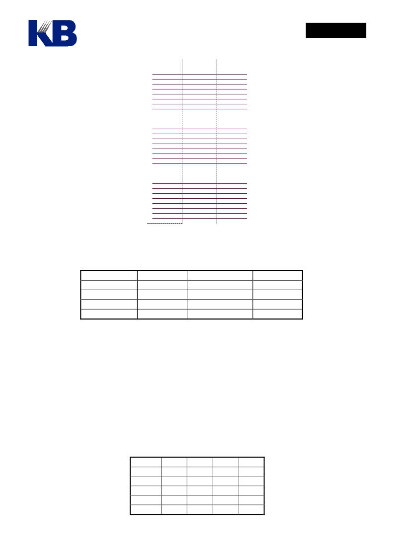
Following table is the setting for MO_LIO[...] and MO_PP[...] and others related to LCD display
setting and pin assignment features.
MO_LIO[…] MO_PP[...]
0
0
1
1
--: Function not available.
xx: Displayable, but may have abnormal leakage current, do not use.
10.
Key Scan Circuit
I/O Port
Open-drain output
Push-pull output
--
--
LCD Pin
--
--
xx
LCD Display
0
1
0
1
The built-in 4x20 hardware keyboard scan circuit helps to reduce the pin counts where application
requires large key matrix and high LCD pixel count as well as the firmware effort. As key-scan pins are
shared with LCD segment and PRTC4 ~ PRTC7 pins, it is advisable to put resistors between segment pins
and key matrix to avoid shorting the segment pins when two or more keys in the same row are pressed
simultaneously. Two key can be detected simultaneously and the first detected key code is stored in
KEY0 register and the second in KEY1 register respectively. The key code for each key location is listed
in the following table.
Key Loc SCNI0 SCNI1 SCNI2 SCNI3
SCNO0
0x80
0xA0
SCNO1
0x81
0xA1
SCNO2
0x82
0xA2
SCNO3
0x83
0xA3
SCNO4
0x84
0xA4
0xC0
0xC1
0xC2
0xC3
0xC4
0xE0
0xE1
0xE2
0xE3
0xE4
相關(guān)PDF資料 |
PDF描述 |
|---|---|
| HE84770 | 8-bit Micro-controller |
| HE84G752B | 8-BIT MICRO-CONTROLLER |
| HE84G761B | 8-BIT MICRO-CONTROLLER |
| HE84G762B | 8-BIT MICRO-CONTROLLER |
| HE84G763B | 8-BIT MICRO-CONTROLLER |
相關(guān)代理商/技術(shù)參數(shù) |
參數(shù)描述 |
|---|---|
| HE84771(S) | 制造商:未知廠家 制造商全稱:未知廠家 功能描述: |
| HE847711(S) | 制造商:未知廠家 制造商全稱:未知廠家 功能描述: |
| HE84772(S) | 制造商:未知廠家 制造商全稱:未知廠家 功能描述: |
| HE847721(S) | 制造商:未知廠家 制造商全稱:未知廠家 功能描述: |
| HE84773(S) | 制造商:未知廠家 制造商全稱:未知廠家 功能描述: |
發(fā)布緊急采購,3分鐘左右您將得到回復(fù)。