- 您現(xiàn)在的位置:買賣IC網(wǎng) > PDF目錄384398 > HE84G761B (King Billion Electronics Co., Ltd.) 8-BIT MICRO-CONTROLLER PDF資料下載
參數(shù)資料
| 型號: | HE84G761B |
| 廠商: | King Billion Electronics Co., Ltd. |
| 英文描述: | 8-BIT MICRO-CONTROLLER |
| 中文描述: | 8位微控制器 |
| 文件頁數(shù): | 14/60頁 |
| 文件大?。?/td> | 594K |
| 代理商: | HE84G761B |
第1頁第2頁第3頁第4頁第5頁第6頁第7頁第8頁第9頁第10頁第11頁第12頁第13頁當前第14頁第15頁第16頁第17頁第18頁第19頁第20頁第21頁第22頁第23頁第24頁第25頁第26頁第27頁第28頁第29頁第30頁第31頁第32頁第33頁第34頁第35頁第36頁第37頁第38頁第39頁第40頁第41頁第42頁第43頁第44頁第45頁第46頁第47頁第48頁第49頁第50頁第51頁第52頁第53頁第54頁第55頁第56頁第57頁第58頁第59頁第60頁
7.
External RAM/Flash Memory
KING BILLION ELECTRONICS CO., LTD
駿
億
電
子
股
份
有
限
公
司
HE84G761B
HE80004 Series
April 25, 2005
This specification is subject to change without notice. Please contact sales person for the latest version before use.
14
V0.92
The external memory devices can be mask ROM, static RAM, or NOR type FLASH memory. Most NOR
type FLASH memory and RAM can be used as external storage for both program and data, so program
can be downloaded to external memory devices for future execution. However, there are some limitations.
When the data is to be written to external devices, the loader must reside in internal program space. In
other words, the loader program must be in internal ROM. When download is completed, the program in
the external memory can be run.
The data written to external memory devices is through a command interface composed of AC, EXMC
and EXMD registers for setting up the memory addresses, switching memory buses, generating read/write
pulse, read/write memory contents, etc. When writing finishes, external memory can be switched back the
external address and data bus for CPU to fetch data and instructions.
Writing to address registers is through a common register AC. Writing to AC will write data to ACL, ACH,
and then ACP in cyclic order. The sequence will be reset by an access to EXMD register. Therefore, it is
advisable to make a dummy read to EXMD register before writing to AC, so that the first write will be
made to ACL.
ACL: Lowest Significant Byte of Address Counter.
ACH: 2
nd
Byte of Address Counter.
ACP: Most Significant Byte of Address Counter.
DNLD: Switch the bus to download bus.
RD: Read pulse control.
WR: Write pulse control.
After address setup, the data can be written to address device through EXMD register. Program must
generate the required write pulse by firmware. The address counter AC will automatically increment with
each read/write access.
The procedure for downloading data from I/O or any other sources, i.e. command mode ROM device is as
follows:
1.
Switch the external memory to download bus by setting the DNLD bit of EXMC register.
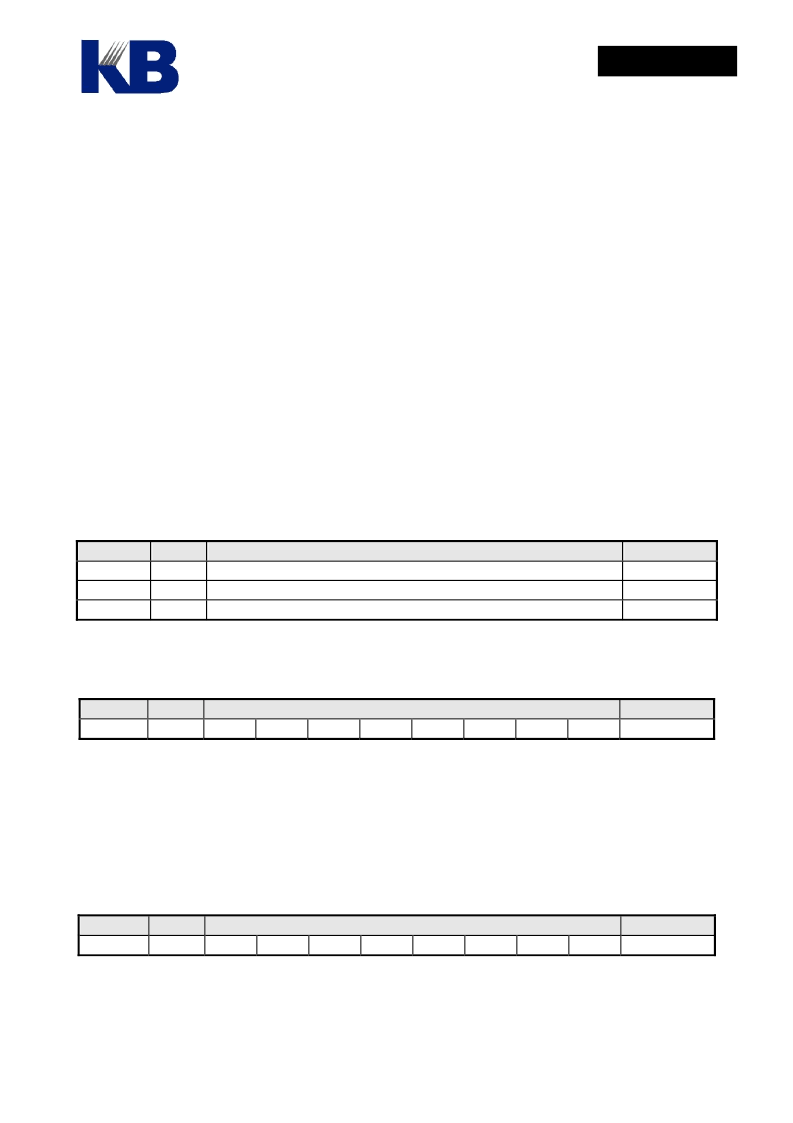
AC
ACL
ACH
ACP
Mode
R/W Address Counter Low for AC7 ~ AC0
R/W Address Counter High for AC15 ~ AC8
R/W Address Counter Page for AC23 ~ AC16
Description
Reset Value
“--------“
“--------“
“--------“
Register Mode Description
EXMC
W
Reset Value
“-----011”
-
-
-
-
-
DNLD
RD
WR
Register Type
EXMD
Description
D4
Reset Value
“--------“
R/W
D7
D6
D5
D3
D2
D1
D0
相關PDF資料 |
PDF描述 |
|---|---|
| HE84G762B | 8-BIT MICRO-CONTROLLER |
| HE84G763B | 8-BIT MICRO-CONTROLLER |
| HE84G770B | 8-BIT MICRO-CONTROLLER |
| HE85750 | 8-bit Micro-controller |
| HE89410 | 8-BIT MICRO-CONTROLLER |
相關代理商/技術參數(shù) |
參數(shù)描述 |
|---|---|
| HE84G762(S) | 制造商:未知廠家 制造商全稱:未知廠家 功能描述: |
| HE84G762B | 制造商:KB 制造商全稱:KB 功能描述:8-BIT MICRO-CONTROLLER |
| HE84G763(S) | 制造商:未知廠家 制造商全稱:未知廠家 功能描述: |
| HE84G763B | 制造商:KB 制造商全稱:KB 功能描述:8-BIT MICRO-CONTROLLER |
| HE84G770(S) | 制造商:未知廠家 制造商全稱:未知廠家 功能描述: |
發(fā)布緊急采購,3分鐘左右您將得到回復。