- 您現(xiàn)在的位置:買賣IC網(wǎng) > PDF目錄370670 > HPWS-FH00 SnapLED 150 LEDs(用于大電流的高光通量LED) PDF資料下載
參數(shù)資料
| 型號(hào): | HPWS-FH00 |
| 英文描述: | SnapLED 150 LEDs(用于大電流的高光通量LED) |
| 中文描述: | SnapLED 150個(gè)LED(用于大電流的高光通量發(fā)光二極管) |
| 文件頁數(shù): | 3/4頁 |
| 文件大?。?/td> | 131K |
| 代理商: | HPWS-FH00 |

3
Optical Characteristics at T
A
= 25
°
C, I
F
= 150 mA, R
θ
J-A
= 100C/W
Color,
Dominant
Wavelength
λ
d
(nm)
[2]
Typ.
621
Total
Included
Angle
θ
0.90 V
(Degrees)
[3]
Typ.
120
70
120
70
Ratio of Luminous
Intensity to
Total Flux
I
v
(mcd)/
Φ
v
(mlm)
Typ.
0.6
2.0
0.6
2.0
Viewing
Angle
2
θ
1/2
(Degrees)
Typ.
85
30
85
30
Peak
Total Flux
Φ
v
(mlm)
[1]
Min.
6000
Wavelength
λ
peak
(nm)
Typ.
630
Device Type
HPWS-TH00
HPWS-FH00
HPWS-TL00
HPWS-FL00
Notes:
1.
Φ
v
is the total luminous flux output as measured with an integrating sphere after the device has stabilized.
2. The dominant wavelength is derived from the CIE Chromaticity Diagram and represents the perceived color of the device.
3.
θ
0.90 V
is the included angle at which 90% of the total luminous flux is captured. See Figure 5.
3000
596
594
Electrical Characteristics at T
A
= 25
°
C
Forward
Voltage
V
F
(Volts)
@ I
F
= 150 mA
Min.
Typ.
2.15
2.55
2.15
2.65
Reverse
Breakdown
V
R
(Volts)
@ I
R
= 100
μ
A
Min.
10
10
Capacitance
C (pF)
V
F
= 0,
f = 1 MHz
Typ.
80
80
Thermal
Resistance
R
θ
J-PIN
(
°
C/W)
Typ.
60
75
Speed of
Response
τ
s
(ns)
[1]
Typ.
20
20
Device Type
HPWS-xH00
HPWS-xL00
Note:
1.
τ
s
is the time constant, e
-t/
τ
s
.
Max.
3.03
3.15
Typ.
20
20
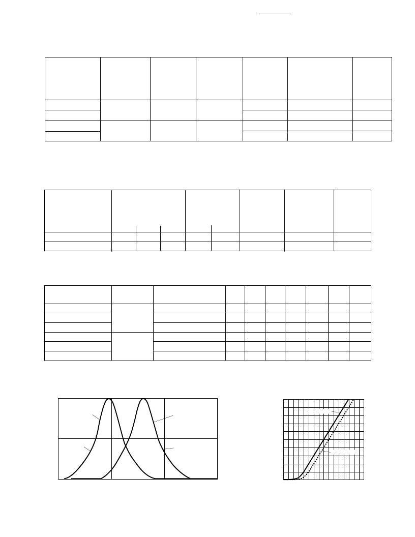
Figure 2. Forward Current vs.
Forward Voltage.
Figure 1. Relative Intensity vs. Wavelength.
F
3.1
200
0
1.5
FORWARD VOLTAGE (V)
1.9 2.1
2.3
140
120
80
60
20
1.7
2.5
180
HPWS-xH00
2.7 2.9
HPWS-xL00
160
100
40
Projected Luminous Flux Category Availability
[1]
Total Flux
Φ
v
(mlm)
@ 150 mA
[2]
Min.
6000
8000
10000
3000
3500
4000
Part Number
HPWS-xH00-L4000
HPWS-xH00-M4000 Red-Orange
HPWS-xH00-N4000
HPWS-xL00-F4000
HPWS-xL00-G4000
HPWS-xL00-H4000
Notes:
1. LEDs will be available at the beginning of indicated years.
2.
Φ
V
is the total luminous flux output as measured with an integrating sphere after the device has stabilized (R
θ
j-a
= 100C/W, T
A
= 25C).
LED Color
TS AlInGaP
1999 2000 2001 2002 2003 2004 2005
TS AlInGap
Amber
WAVELENGTH (nm)
R
550
600
650
700
1.0
0.5
0
HPWS-xH00
HPWS-xL00
AMBER
RED-ORANGE
相關(guān)PDF資料 |
PDF描述 |
|---|---|
| HPWS-FL00 | SnapLED 150 LEDs(用于大電流的高光通量LED) |
| HPWT-BD00 | Super Flux LEDs(超高光通量LED) |
| HPWT-DH00 | Super Flux LEDs(超高光通量LED) |
| HPWT-BH00 | Super Flux LEDs(超高光通量LED) |
| HPWT-BL00 | Super Flux LEDs(超高光通量LED) |
相關(guān)代理商/技術(shù)參數(shù) |
參數(shù)描述 |
|---|---|
| HPWS-FH00-L4000 | 制造商:Philips Lumileds 功能描述:SnapLED 150 Emitter Low Power LED Red Orange 150 mA 2.8 V 11 Lumens |
| HPWS-FH00-M4000 | 制造商:Philips Lumileds 功能描述:SnapLED 150 Low Power LED Red Orange 150 mA 2.8 V 11 Lumens |
| HPWS-FH77 | 制造商:LUMILEDS 制造商全稱:LUMILEDS 功能描述:SnapLED 150 |
| HPWS-FH77-U36GD | 制造商:Philips Lumileds 功能描述: |
| HPWS-FH99-N20D0 | 制造商:Philips Lumileds 功能描述:HPWS Series SnapLED 150 Red Orange 150 mA 2.8 V 11 lm Low Power LED |
發(fā)布緊急采購,3分鐘左右您將得到回復(fù)。