- 您現(xiàn)在的位置:買賣IC網(wǎng) > PDF目錄370699 > HSMS-282P Surface Mount RF Schottky Barrier Diodes(表貼型射頻肖特基勢(shì)壘二極管) PDF資料下載
參數(shù)資料
| 型號(hào): | HSMS-282P |
| 英文描述: | Surface Mount RF Schottky Barrier Diodes(表貼型射頻肖特基勢(shì)壘二極管) |
| 中文描述: | 表面貼裝射頻肖特基二極管(表貼型射頻肖特基勢(shì)壘二極管) |
| 文件頁數(shù): | 8/12頁 |
| 文件大?。?/td> | 141K |
| 代理商: | HSMS-282P |

8
lower cost solution is available
[4]
.
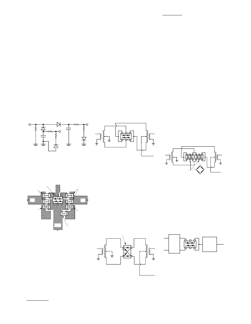
Illustrated schematically in
Figure 19, this circuit uses diode
D2 and its associated passive
components to cancel all even
order harmonics at the detector’s
RF input. Diodes D3 and D4
provide temperature compensa-
tion as described above. All four
diodes are contained in a single
HSMS- 282R package, as illus-
trated in the layout shown in
Figure 20.
RF in
D1
R1
V+
R2
D3
C1
V–
R4
D4
C1 = C2
≈
100 pF
R1 = R2 = R3 = R4 = 4.7 K
D1 & D2 & D3 & D4 = HSMS-282R
C2
D2
68
R3
Figure 19. Schematic of Suppressed
Harmonic Detector.
HSMS-282R
4.7 K
4.7 K
100 pF
100 pF
68
V–
RF in
V+
Figure 20. Layout of Suppressed
Harmonic Detector.
Note that the forgoing discussion
refers to the output voltage being
extracted at point V+ with respect
to ground. If a differential output
is taken at V+ with respect to V-,
the circuit acts as a voltage
doubler.
Mixer Applications
The HSMS-282x family, with its
wide variety of packaging, can be
used to make excellent mixers at
frequencies up to 6 GHz.
The HSMS-2827 ring quad of
matched diodes (in the SOT-143
package) has been designed for
double balanced mixers. The
smaller (SOT-363) HSMS-282R ring
quad can similarly be used, if the
quad is closed with external
connections as shown in Figure 21.
HSMS-282R
IF out
RF in
LO in
Figure 21. Double Balanced Mixer.
Both of these networks require a
crossover or a three dimensional
circuit. A planar mixer can be
made using the SOT-143 cross-
over quad, HSMS-2829, as shown
in Figure 22. In this product, a
special lead frame permits the
crossover to be placed inside the
plastic package itself, eliminating
the need for via holes (or other
measures) in the RF portion of
the circuit itself.
HSMS-2829
IF out
RF in
LO in
Figure 22. Planar Double Balanced
Mixer.
A review of Figure 21 may lead to
the question as to why the
HSMS-282R ring quad is open on
the ends. Distortion in double
balanced mixers can be reduced
if LO drive is increased, up to the
point where the Schottky diodes
are driven into saturation. Above
this point, increased LO drive will
not result in improvements in
distortion. The use of expensive
high barrier diodes (such as those
fabricated on GaAs) can take
advantage of higher LO drive
power, but a lower cost solution
is to use a eight (or twelve) diode
ring quad. The open design of the
HSMS-282R permits this to easily
be done, as shown in Figure 23.
HSMS-282R
IF out
RF in
LO in
Figure 23. Low Distortion Double
Balanced Mixer.
This same technique can be used
in the single-balanced mixer.
Figure 24 shows such a mixer,
with two diodes in each spot
normally occupied by one. This
mixer, with a sufficiently high LO
drive level, will display low
distortion.
HSMS-282R
180
°
hybrid
IF out
LO in
RF in
Low pass
filter
Figure 24. Low Distortion Balanced
Mixer.
[4]
Alan Rixon and Raymond W. Waugh, “A Suppressed Harmonic Power Detector for Dual
Band ‘Phones,” to be published.
相關(guān)PDF資料 |
PDF描述 |
|---|---|
| HSMS-282R | Surface Mount RF Schottky Barrier Diodes(表貼型射頻肖特基勢(shì)壘二極管) |
| HSMS-285A | Surface Mount Microwave Schottky Detector Diodes in SOT-323(表貼型微波肖特基檢測(cè)二極管(SOT-323封裝)) |
| HSMS-286A | Surface Mount Microwave Schottky Detector Diodes in SOT-323(表貼型微波肖特基檢測(cè)二極管(SOT-323封裝)) |
| HSMS-286K | Surface Mount RF Schottky Detector Diodes in SOT-363(表貼型射頻肖特基檢測(cè)二極管(SOT-363封裝)) |
| HSMS-286L | Surface Mount RF Schottky Detector Diodes in SOT-363(表貼型射頻肖特基檢測(cè)二極管(SOT-363封裝)) |
相關(guān)代理商/技術(shù)參數(shù) |
參數(shù)描述 |
|---|---|
| HSMS-282P-BLK | 制造商:AGILENT 制造商全稱:AGILENT 功能描述:Surface Mount RF Schottky Barrier Diodes |
| HSMS282P-BLK | 制造商:未知廠家 制造商全稱:未知廠家 功能描述:BRIDGE/RING DIODE ARRAY|TSOP |
| HSMS-282P-BLKG | 功能描述:肖特基二極管與整流器 15 VBR 1 pF RoHS:否 制造商:Skyworks Solutions, Inc. 產(chǎn)品:Schottky Diodes 峰值反向電壓:2 V 正向連續(xù)電流:50 mA 最大浪涌電流: 配置:Crossover Quad 恢復(fù)時(shí)間: 正向電壓下降:370 mV 最大反向漏泄電流: 最大功率耗散:75 mW 工作溫度范圍:- 65 C to + 150 C 安裝風(fēng)格:SMD/SMT 封裝 / 箱體:SOT-143 封裝:Reel |
| HSMS-282P-BLKG | 制造商:Avago Technologies 功能描述:SCHOTTKY DIODE |
| HSMS-282P-TR1 | 制造商:AGILENT 制造商全稱:AGILENT 功能描述:Surface Mount RF Schottky Barrier Diodes |
發(fā)布緊急采購,3分鐘左右您將得到回復(fù)。