- 您現(xiàn)在的位置:買賣IC網(wǎng) > PDF目錄370699 > HSMS-286L Surface Mount RF Schottky Detector Diodes in SOT-363(表貼型射頻肖特基檢測二極管(SOT-363封裝)) PDF資料下載
參數(shù)資料
| 型號: | HSMS-286L |
| 英文描述: | Surface Mount RF Schottky Detector Diodes in SOT-363(表貼型射頻肖特基檢測二極管(SOT-363封裝)) |
| 中文描述: | 表面貼裝RF肖特基二極管檢測器采用SOT - 363(表貼型射頻肖特基檢測二極管(采用SOT - 363封裝)) |
| 文件頁數(shù): | 7/12頁 |
| 文件大小: | 96K |
| 代理商: | HSMS-286L |

7
capacitance and the video
resistance. Of these five elements
of the diode’s equivalent circuit,
the four parasitics are constants
and the video resistance is a
function of the current flowing
through the diode.
R
V
≈
26,000
I
S
+ I
b
where
I
S
= diode saturation current
in
μ
A
I
b
= bias current in
μ
A
Saturation current is a function of
the diode’s design,
[5]
and it is a
constant at a given temperature.
For the HSMS-285X series, it is
typically 3 to 5
μ
A at 25
°
C. For the
medium barrier HSMS-2860 family,
saturation current at room
temperature is on the order of
50 nA.
Together, saturation and (if used)
bias current set the detection
sensitivity, video resistance and
input RF impedance of the
Schottky detector diode. Since no
external bias is used with the
HSMS-285
a
series, a single transfer
curve at any given frequency is
obtained, as shown in Figure 4.
Where bias current is used, some
tradeoff in sensitivity and square
law dynamic range is seen, as
shown in Figure 6 and described in
reference [3].
The most difficult part of the
design of a detector circuit is the
input impedance matching
network. A discussion of such
circuits can be found in the data
sheet for the HSMS-285
a
/HSMS-
286
a
single SOT-323 detector
diodes (Hewlett-Packard
publication 5965-4704E).
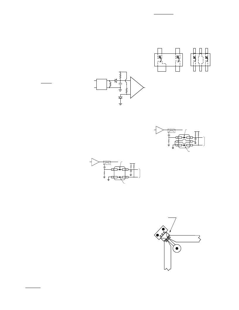
Six Lead Circuits
The differential detector is often
used to provide temperature
compensation for a Schottky
detector, as shown in Figure 13.
matching
network
differential
amplifier
bias
Figure 13. Differential Detector.
These circuits depend upon the
use of two diodes having matched
V
f
characteristics over all
operating temperatures. This is
best achieved by using two diodes
in a single package, such as the
SOT-143 HSMS-2865 as shown in
Figure 14.
toamplifier
V
s
ddiode
reference diode
PA
HSMS-2865
Figure 14. Conventional Differen-
tial Detector.
In high power differential detec-
tors, RF coupling from the detec-
tor diode to the reference diode
produces a rectified voltage in the
latter, resulting in errors.
Isolation between the two diodes
can be obtained by using the
HSMS-286K diode with leads 2 and
5 grounded. The difference
between this product and the
conventional HSMS-2865 can be
seen in Figure 15.
HSMS-2865
SOT-143
HSMS-286K
SOT-363
3
4
6
5
4
1
1
2
2
3
Figure 15. Comparing Two Diodes.
The HSMS-286K, with leads 2 and
5 grounded, offers some isolation
from RF coupling between the
diodes. This product is used in a
differential detector as shown in
Figure 16.
toamplifier
V
s
ddiode
reference diode
PA
HSMS-286K
Figure 16. High Isolation
Differential Detector.
In order to achieve the maximum
isolation, the designer must take
care to minimize the distance
from leads 2 and 5 and their
respective ground via holes. In
addition, the ground structure
should isolate the input RF and
reference lines, as shown in
Figure 17.
HSMS-286K
RF Input
ref
Figure 17. Diode Mounting,
HSMS-286K.
[5]
Hewlett-Packard Application Note 969,
An Optimum Zero Bias Schottky Detector Diode.
相關(guān)PDF資料 |
PDF描述 |
|---|---|
| HSMS-286P | Surface Mount RF Schottky Detector Diodes in SOT-363(表貼型射頻肖特基檢測二極管(SOT-363封裝)) |
| HSMS-286R | Surface Mount RF Schottky Detector Diodes in SOT-363(表貼型射頻肖特基檢測二極管(SOT-363封裝)) |
| HSMS-8205 | Surface Mount Microwave Schottky Mixer Diodes(表貼型微波肖特基混頻二極管(成對分離)) |
| HSMS-8207 | Surface Mount Microwave Schottky Mixer Diodes(表貼型微波肖特基混頻二極管(四路振鈴)) |
| HSMS-8101 | Surface Mount Microwave Schottky Mixer Diodes(表貼型微波肖特基混頻二極管(單路)) |
相關(guān)代理商/技術(shù)參數(shù) |
參數(shù)描述 |
|---|---|
| HSMS-286L/P/R | 制造商:未知廠家 制造商全稱:未知廠家 功能描述:Surface Mount RF Schottky Detector Diodes in SOT-363 (SC-70. 6 Lead) (101K in pdf) |
| HSMS286L-BLK | 制造商:未知廠家 制造商全稱:未知廠家 功能描述:ARRAY OF INDEPENDENT DIODES|TSOP |
| HSMS-286L-BLKG | 功能描述:射頻檢測器 4 VBR 0.3 pF RoHS:否 制造商:Skyworks Solutions, Inc. 配置: 頻率范圍:650 MHz to 3 GHz 最大二極管電容: 最大工作溫度:+ 85 C 最小工作溫度:- 40 C 封裝 / 箱體:SC-88 封裝:Reel |
| HSMS286L-TR1 | 制造商:未知廠家 制造商全稱:未知廠家 功能描述:ARRAY OF INDEPENDENT DIODES|TSOP |
| HSMS-286L-TR1G | 功能描述:射頻檢測器 4 VBR 0.3 pF RoHS:否 制造商:Skyworks Solutions, Inc. 配置: 頻率范圍:650 MHz to 3 GHz 最大二極管電容: 最大工作溫度:+ 85 C 最小工作溫度:- 40 C 封裝 / 箱體:SC-88 封裝:Reel |
發(fā)布緊急采購,3分鐘左右您將得到回復(fù)。