- 您現(xiàn)在的位置:買賣IC網(wǎng) > PDF目錄371896 > HSP43220VC-33 (INTERSIL CORP) Decimating Digital Filter PDF資料下載
參數(shù)資料
| 型號: | HSP43220VC-33 |
| 廠商: | INTERSIL CORP |
| 元件分類: | 數(shù)字信號處理外設(shè) |
| 英文描述: | Decimating Digital Filter |
| 中文描述: | 16-BIT, DSP-DIGITAL FILTER, PQFP100 |
| 封裝: | MQFP-100 |
| 文件頁數(shù): | 6/19頁 |
| 文件大?。?/td> | 190K |
| 代理商: | HSP43220VC-33 |
3-199
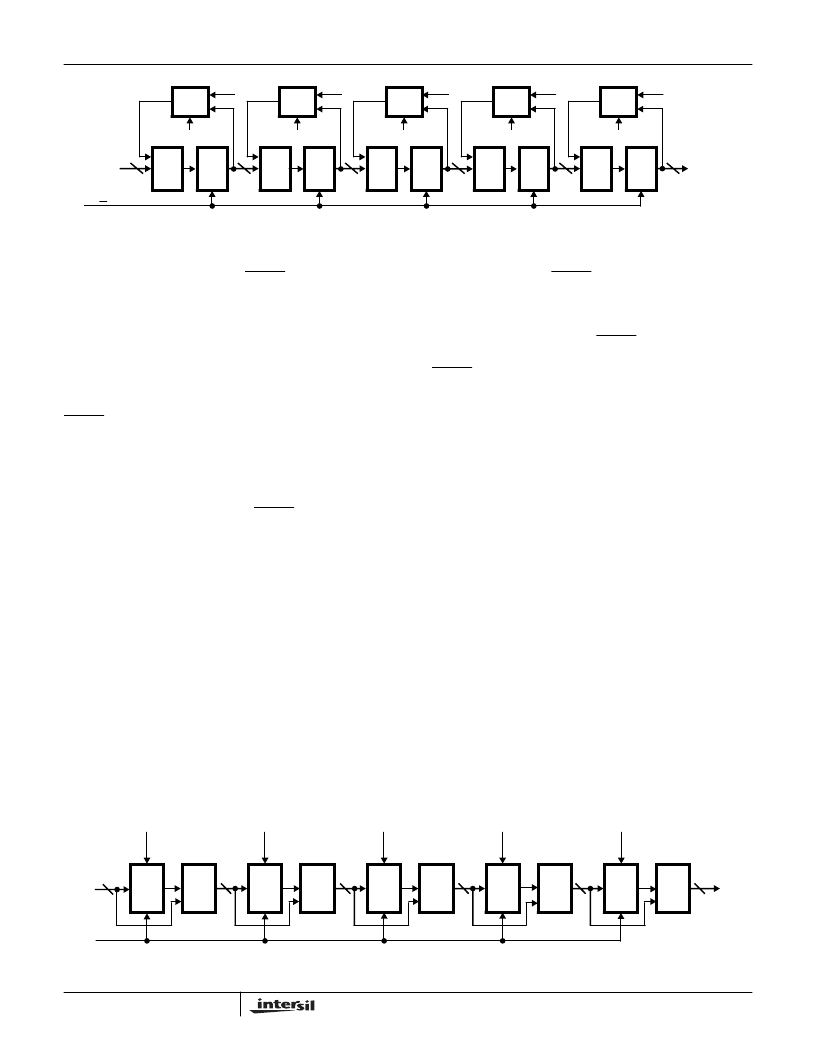
There are three signals that control the integrator section;
they are H_STAGES, H_BYP and RESET. In Figure 2 these
control signals have been decoded and are labelled
INT_EN1 - INT_EN5. The order of the filter is loaded via the
control bus and is called H_STAGES. H_STAGES is
decoded to provide the enables for each integrator stage.
When a given integrator stage is selected, the feedback path
is enabled and the integrator accumulates the current data
sample with the previous sum. The integrator section can be
put in bypass mode by the H_BYP bit. When H_BYP or
RESET is asserted, the feedback paths in all integrator
stages are cleared.
Decimation Register
The output of the Integrator section is latched into the
Decimation Register by CK_DEC. The output of the
Decimation register is cleared when RESET is asserted. The
HDF decimation rate = H_DRATE +1, which is defined as
H
DEC
for convenience.
Comb Filter Section
The output of the Decimation Register is passed to the
Comb Filter Section. The Comb section consists of 5
cascaded Comb filters or differentiators. Each Comb filter
section calculates the difference between the current and
previous integrator output. Each Comb filter consists of a
register which is clocked by CK_DEC, followed by an
subtractor, where the subtractor calculates the difference
between the input and output of the register. Bit truncations
are done at each stage as shown in Figure 3. The first
stage bit width is 26 bits and the output of the fifth stage is
19 bits.
There are three signals that control the Comb Filter; H_
STAGES, H_BYP and RESET. In Figure 3 these control
signals are decoded as COMB_EN1 - COMB_EN5. The
order of the Comb filter is controlled by H_STAGES, which is
programmed over the control bus. H_BYP is used to put the
comb section in bypass mode. RESET causes the register
output in each Comb stage to be cleared. The H_ BYP and
RESET control pins, when asserted force the output of all
registers to zero so data is passed through the subtractor
unaltered. When the H_STAGES control bits enable a given
stage the output of the register is subtracted from the input.
It is important to note that the Comb filter section has a speed
limitation. The Input sampling rate divided by the decimation
factor in the HDF (CK_IN/H
DEC
) should not exceed 4MHz.
Violating this condition causes the output of the filter to be
incorrect. When the HDF is put in bypass mode this limitation
does not apply. Equation 1 describes the relationship between
F_TAPS, F_DRATE, H_DRATE, CK_IN and FIR_CK.
Rounder
The filter accuracy is limited by the 16-bit data input. To
maintain the maximum accuracy, the output of the comb is
rounded to 16 bits.
The Rounder performs a symmetric round of the 19-bit
output of the last Comb stage. Symmetric rounding is done
to prevent the synthesis of a 0Hz spectral component by the
rounding process and thus causing a reduction in spurious
free dynamic range. Saturation logic is also provided to
prevent roll over from the largest positive value to the most
negative value after rounding. The output of the last comb
filter stage in the HDF section has a 16-bit integer portion
with a 3-bit fractional part in 2's complement format.
FIGURE 2. INTEGRATOR
MUX
INT_EN5
REG
66
63
0
MUX
INT_EN4
REG
53
0
MUX
INT_EN3
REG
43
0
MUX
INT_EN2
REG
35
0
MUX
INT_EN1
REG
26
0
FROM
SHIFTER
TO
DECIMATION
REGISTER
CK
IN
∑
∑
∑
∑
∑
FIGURE 3. COMB FILTER
B
A
A-B
COMB_EN5
RESET
REG
B
A
A-B
COMB_EN4
22
B
A
A-B
COMB_EN3
21
B
A
A-B
COMB_EN2
20
B
A
A-B
COMB_EN1
19
DECI-
MATION
REGISTER
26
19
TO
ROUNDER
CK_DEC
RESET
REG
RESET
REG
RESET
REG
RESET
REG
FROM
HSP43220
相關(guān)PDF資料 |
PDF描述 |
|---|---|
| HSP43220 | RESISTOR 47 OHM 20W TO220 |
| HSP43220883 | Decimating Digital Filter |
| HSP43220JC-25 | CONN MEMORY CARD NORMAL TOP PCB |
| HSP43220JC-33 | CONNECTOR: SECURE DIGITAL MEMORY CARD |
| HSP43481GC-20 | Digital Filter |
相關(guān)代理商/技術(shù)參數(shù) |
參數(shù)描述 |
|---|---|
| HSP43481 | 制造商:INTERSIL 制造商全稱:Intersil Corporation 功能描述:Digital Filter |
| HSP43481/883 | 制造商:INTERSIL 制造商全稱:Intersil Corporation 功能描述:Digital Filter |
| HSP43481883 | 制造商:INTERSIL 制造商全稱:Intersil Corporation 功能描述:Digital Filter |
| HSP43481GC-20 | 制造商:INTERSIL 制造商全稱:Intersil Corporation 功能描述:Digital Filter |
| HSP43481GC-25 | 制造商:INTERSIL 制造商全稱:Intersil Corporation 功能描述:Digital Filter |
發(fā)布緊急采購,3分鐘左右您將得到回復(fù)。