- 您現(xiàn)在的位置:買賣IC網(wǎng) > PDF目錄383075 > HSP50214A (Intersil Corporation) Programmable Downconverter PDF資料下載
參數(shù)資料
| 型號(hào): | HSP50214A |
| 廠商: | Intersil Corporation |
| 英文描述: | Programmable Downconverter |
| 中文描述: | 可編程變頻器 |
| 文件頁數(shù): | 48/60頁 |
| 文件大?。?/td> | 467K |
| 代理商: | HSP50214A |
第1頁第2頁第3頁第4頁第5頁第6頁第7頁第8頁第9頁第10頁第11頁第12頁第13頁第14頁第15頁第16頁第17頁第18頁第19頁第20頁第21頁第22頁第23頁第24頁第25頁第26頁第27頁第28頁第29頁第30頁第31頁第32頁第33頁第34頁第35頁第36頁第37頁第38頁第39頁第40頁第41頁第42頁第43頁第44頁第45頁第46頁第47頁當(dāng)前第48頁第49頁第50頁第51頁第52頁第53頁第54頁第55頁第56頁第57頁第58頁第59頁第60頁
48
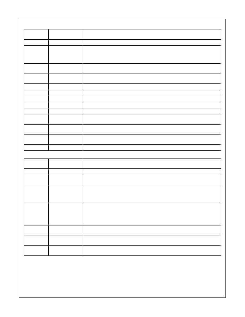
CONTROL WORD 7: HB, FIR CONFIGURATION (SYNCHRONIZED TO PROCCLK)
BIT
POSITION
FUNCTION
DESCRIPTION
31-22
Reserved
Reserved.
21
Enable External
Filter Sync
0- The SYNCIN2 pin has no effect on the halfband and FIR filters.
1- When the SYNCIN2 pin is asserted, the filter control circuitry in the halfband filters, the FIR,
the resampler, and the discriminator are reset. SYNCIN2 can be used to synchronize the com-
putations of the filters in multiple parts for the alignment (see Synchronization Section).
20
Halfband (HB)
Bypass
1- Bypass Halfband Filters.
0- Enable HB Filters (at least one HB must be enabled).
19
HB5 Enable
0- Disables HB number 5 (the last in the cascade).
1- Enables HB filter number 5.
18
HB4 Enable
Setting this bit enables HB filter number 4.
17
HB3 Enable
Setting this bit enables HB filter number 3.
16
HB2 Enable
Setting this bit enables HB filter number 2.
15
HB1 Enable
Setting this bit enables HB filter number 1.
14-11
FIR Decimation
Load decimation from 1-16, where 0000 = 16. Bit 14 is the MSB.
10
FIR Real/Complex
0- Complex Filter.
1- Dual Real Filters.
9
FIR Sym Type
0- Odd Symmetry.
1- Even Symmetry.
8
FIR Symmetry
0- Symmetric Filters.
1- Asymmetric Filters.
7-0
FIR Taps
Number of taps in the FIR filter. Range is 1 to 255, where 0000000 is invalid.
CONTROL WORD 8: AGC CONFIGURATION 1 (SYNCHRONIZED TO PROCCLK)
BIT
POSITION
FUNCTION
DESCRIPTION
31-30
Reserved
Reserved.
29
Sync AGC Updates
to SYNCIN2
When this bit is 1, the SYNCIN2 pin loads the contents of the master registers into the AGC
accumulator.
28-16
Threshold
The magnitude measurement out of the cartesian to polar converter is subtracted from this val-
ue to get the gain error. A gain of 1.647 in the cartesian to polar conversion that must be taken
into account when computing this threshold. These bits are weighted -2
2
down to 2
-10
. Bit 28 is
the MSB.
15-12
Loop Gain 1
Mantissa
Selected when AGCGNSEL = 1. These bits, MMMM, together with the exponent bits, EEEE
(11-8), set the loop gain for the AGC loop. The gain adjustment per output sample is:
1.5dB (Threshold -[Magnitude * 1.6]) 0.MMMM * 2
-(15 - EEEE)
where magnitude ranges from 0
to 1.414 and the threshold is programmed in bits 28-16. The decimal value for the mantissa is
calculated as DEC(MMMM)/16. Bit 15 is the MSB.
11-8
Loop Gain 1
Exponent
Selected when AGCGNSEL = 1. These bits are EEEE. See description of bits 15-12. Bit 11 is
the MSB.
7-4
Loop Gain 0 Mantissa
Selected when AGCGNSEL = 0. These bits are MMMM. See description for bits 15-12. Same
equations are used for Loop 0. Bit 7 is the MSB.
3-0
Loop Gain 0
Exponent
Selected when AGCGNSEL = 0. These bits are EEEE. See description for bits 15-12. Same
equations are used for Loop 0. Bit 3 is the MSB.
HSP50214A
相關(guān)PDF資料 |
PDF描述 |
|---|---|
| HSP50214AVC | Programmable Downconverter |
| HSP50214AVI | Programmable Downconverter |
| HSP50214B | Programmable Downconverter |
| HSP50214BVC | Programmable Downconverter |
| HSP50214BVI | Programmable Downconverter |
相關(guān)代理商/技術(shù)參數(shù) |
參數(shù)描述 |
|---|---|
| HSP50214AVC | 制造商:Rochester Electronics LLC 功能描述:- Bulk |
| HSP50214AVI | 制造商:INTERSIL 制造商全稱:Intersil Corporation 功能描述:Programmable Downconverter |
| HSP50214B | 制造商:INTERSIL 制造商全稱:Intersil Corporation 功能描述:Programmable Downconverter |
| HSP50214B_07 | 制造商:INTERSIL 制造商全稱:Intersil Corporation 功能描述:Programmable Downconverter |
| HSP50214BVC | 功能描述:上下轉(zhuǎn)換器 120L MQFP COMTEMP 14-BIT PROGRAMMABLE DOWNCONVERTER 65MSPS RoHS:否 制造商:Texas Instruments 產(chǎn)品:Down Converters 射頻:52 MHz to 78 MHz 中頻:300 MHz LO頻率: 功率增益: P1dB: 工作電源電壓:1.8 V, 3.3 V 工作電源電流:120 mA 最大功率耗散:1 W 最大工作溫度:+ 85 C 安裝風(fēng)格:SMD/SMT 封裝 / 箱體:PQFP-128 |
發(fā)布緊急采購,3分鐘左右您將得到回復(fù)。