- 您現(xiàn)在的位置:買賣IC網(wǎng) > PDF目錄370723 > HTR6516R2 (Hitachi,Ltd.) SFP TRANSCEIVER for Gigabit Ethernet Fibre Channel PDF資料下載
參數(shù)資料
| 型號(hào): | HTR6516R2 |
| 廠商: | Hitachi,Ltd. |
| 英文描述: | SFP TRANSCEIVER for Gigabit Ethernet Fibre Channel |
| 中文描述: | SFP收發(fā)器千兆以太網(wǎng)光纖通道 |
| 文件頁(yè)數(shù): | 13/16頁(yè) |
| 文件大?。?/td> | 569K |
| 代理商: | HTR6516R2 |
第1頁(yè)第2頁(yè)第3頁(yè)第4頁(yè)第5頁(yè)第6頁(yè)第7頁(yè)第8頁(yè)第9頁(yè)第10頁(yè)第11頁(yè)第12頁(yè)當(dāng)前第13頁(yè)第14頁(yè)第15頁(yè)第16頁(yè)

Page 12 of 15
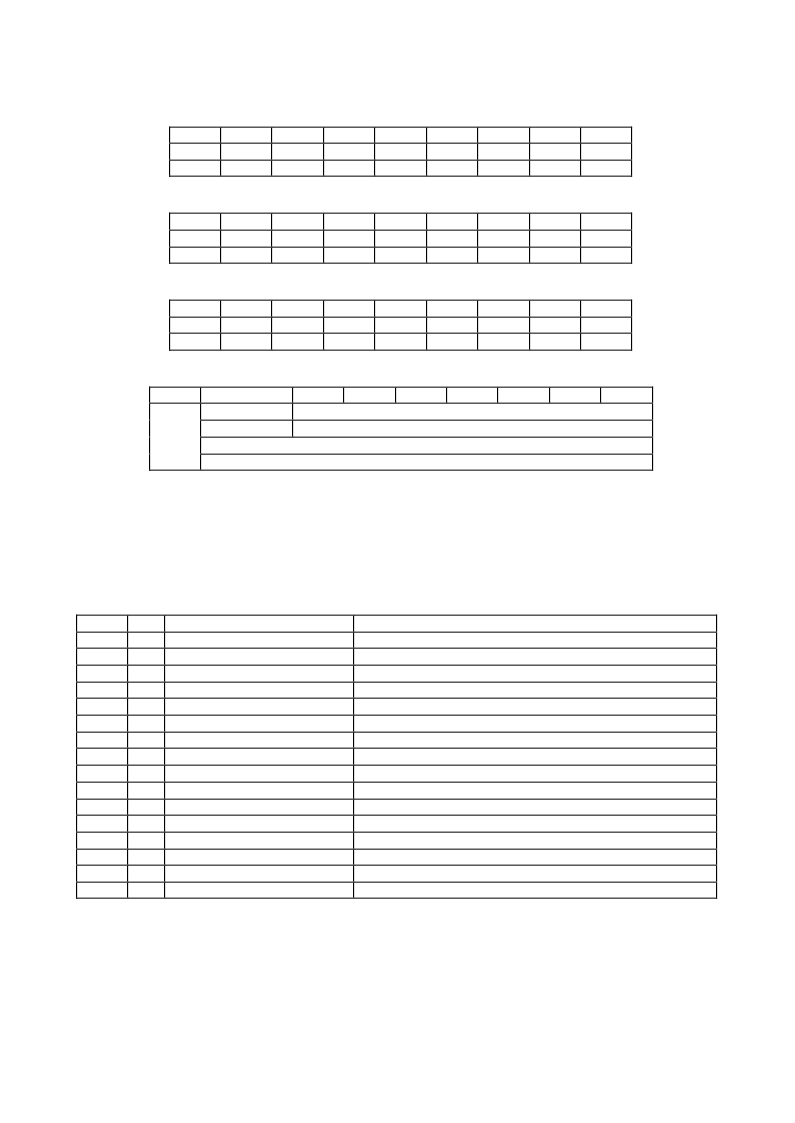
Table 6.3a 16-Bit Signed 2's Complement Number (MSB at low address)
Bit 7
Bit 6
Bit 5
Bit 4
MSB
SIGN
2
14
2
13
2
12
LSB
2
7
2
6
2
5
2
4
Bit 3
2
11
2
3
Bit 2
2
10
2
2
Bit 1
2
9
2
1
Bit 0
2
8
2
0
Table 6.3b 16-bit Unsigned Number (MSB at low address)
Bit 7
Bit 6
Bit 5
Bit 4
2
15
2
14
2
13
2
12
2
7
2
6
2
5
2
4
Bit 3
2
11
2
3
Bit 2
2
10
2
2
Bit 1
2
9
2
1
Bit 0
2
8
2
0
MSB
L SB
Table 6.3c Unsigned Fixed-Point Number (MSB at low address)
Bit 7
Bit 6
Bit 5
Bit 4
MSB
2
7
2
6
2
5
LSB
2
-1
2
-2
2
-3
Bit 3
2
3
2
-5
Bit 2
2
2
2
-6
Bit 1
2
1
2
-7
Bit 0
2
0
2
-8
2
4
2
-4
Table 6.3d IE E E-754 Single Precision Floating-Point Number (MSB at low address)
Bit 7
Bit 6
Bit 5
MSB
SIGN
E XPONE NT
MANTISSA
LSB
MANTISSA
Bit 4
Bit 3
Bit 2
Bit 1
Bit 0
E XPONE NT
MANTISSA
This transceiver is implemented two optional status bits, "Logic States" at byte 110 (0xA2) and "A/D
Updated" at byte 111 (0xA2) as shown in Table 6.4. "A/D updated" status bits allows the user to
verify if an update from the analog-digital conversion has occurred to the measured values,
temperature, Vcc, laser bias, Tx power and Rx power. The user writes the byte to 0x00. Once a
conversion is complete for a given value, its bit will change to '1'.
Table 6.4 Optional Status Bits / 2 wire address 1010001X (0xA2)
Name
Tx Disable State
Optional digital state of the Tx Disable input pin.
Soft Tx Disable Control
Not supported (set to 0).
Reserved
Set to 0.
Rx Rate Select State
Not supported (set to 1).
Soft Rate Select Control
Not supported (set to 0).
Tx Fault
Optional digital state of the Tx Fault output pin.
LOS
Optional digital state of the LOS output pin.
Power on Logic
Bit will be 0 when the analog monitoring is active.
Temp A/D Valid
Indicates A/D value in Bytes 96/97 is valid.
Vcc A/D Valid
Indicates A/D value in Bytes 98/99 is valid.
Laser Bias A/D Valid
Indicates A/D value in Bytes 100/101 is valid.
Tx Power A/D Valid
Indicates A/D value in Bytes 102/103 is valid.
Rx Power A/D Valid
Indicates A/D value in Bytes 104/105 is valid.
Reserved
Set to 0.
Reserved
Set to 0.
Reserved
Set to 0.
Byte
110
110
110
110
110
110
110
110
111
111
111
111
111
111
111
111
Bit
7
6
5
4
3
2
1
0
7
6
5
4
3
2
1
0
Description
相關(guān)PDF資料 |
PDF描述 |
|---|---|
| HTR6516 | SFP TRANSCEIVER for Gigabit Ethernet Fibre Channel |
| HTR6545 | SFF TRANSCEIVER |
| HTY75-P | Current Transducer HTY 50~100-P |
| HTY50-P | Current Transducer HTY 50~100-P |
| HTY100-P | Current Transducer HTY 50~100-P |
相關(guān)代理商/技術(shù)參數(shù) |
參數(shù)描述 |
|---|---|
| HTR6543 | 制造商:Hitachi 功能描述: |
| HTR6545 | 制造商:HITACHI 制造商全稱:Hitachi Semiconductor 功能描述:SFF TRANSCEIVER |
| HTRC110 | 制造商:PHILIPS 制造商全稱:NXP Semiconductors 功能描述:HITAG reader chip |
| HTRC11001 | 制造商:PHILIPS 制造商全稱:NXP Semiconductors 功能描述:HITAG reader chip |
| HTRC11001AD-T | 功能描述:RFID應(yīng)答器 RFID HITAG READER RoHS:否 制造商:Murata 存儲(chǔ)容量:512 bit 工作溫度范圍:- 40 C to + 85 C 安裝風(fēng)格:SMD/SMT 封裝 / 箱體: 封裝:Reel |
發(fā)布緊急采購(gòu),3分鐘左右您將得到回復(fù)。