- 您現(xiàn)在的位置:買賣IC網(wǎng) > PDF目錄370738 > HY-53 (PerkinElmer Inc.) Thyratrons PDF資料下載
參數(shù)資料
| 型號: | HY-53 |
| 廠商: | PerkinElmer Inc. |
| 英文描述: | Thyratrons |
| 中文描述: | 閘流管 |
| 文件頁數(shù): | 2/6頁 |
| 文件大小: | 49K |
| 代理商: | HY-53 |

How a Thyratron works
The operation of the device can
be divided into three phases: trig-
gering and commutation (closure),
steady-state conduction, and
recovery (opening), each of which
is discussed below.
Triggering and Commutation
When a suitable positive trigger-
ing pulse of energy is applied to
the grid, a plasma forms in the
grid-cathode region from elec-
trons. This plasma passes through
the apertures of the grid structure
and causes electrical breakdown
in the high-voltage region
between the grid and the anode.
This begins the process of thyra-
tron switching (also called com-
mutation). The plasma that is
formed between the grid and the
anode diffuses back through the
grid into the grid-cathode space.
"Connection" of the plasma in the
anode-grid space with the plasma
in the cathode-grid space com-
pletes the commutation process.
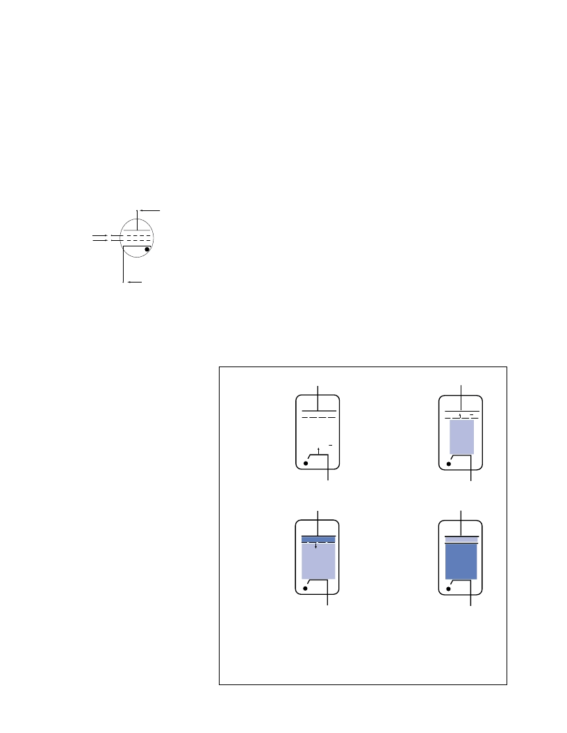
The commutation process is sim-
ply modeled as shown in Figure 2.
The time interval between trigger
breakdown of the grid-cathode
region and complete closure of
the thyratron is called the anode
delay time. It is typically 100-200
nanoseconds for most tube types.
During commutation, a high volt-
age spike appears at the grid of
the thyratron. This spike happens
in the time it takes for the plasma
in the grid-anode space to "con-
nect" to the plasma in the grid-
cathode space. During this time,
the anode is momentarily "con-
nected" to the grid thereby caus-
ing the grid to assume a voltage
nearly that of the anode’s.
Although the grid spike voltage is
brief in duration, usually less than
100 nS, it can damage the grid
driver circuit unless measures
are taken to suppress the spike
before it enters the grid driver cir-
cuit. The location of the grid spike
suppression circuit is shown in
Figure 3, Grid Circuit.
Figure 4, Typical Grid Spike
Suppression Circuits, shows the
more common methods used to
protect the grid driver circuit. In
using any of these types of cir-
cuits, care must be exercised to
assure that the Grid Driver Circuit
pulse is not attenuated in an unac-
ceptable manner. The values for
the circuit components are
dependent on the characteristics
of the thyratron being driven, the
ANODE
CONTROL GRID (G2)
AUXILIARY GRID (G1)
CATHODE
Figure 1. Thyratron with auxiliary grid
(heater detail not shown)
e
e
1. Trigger pulse applied
to control grid.
2. Grid-cathode breakdown.
3. Electrons from grid-cathode
region create a dense plasma
in the grid-anode region. The
plasma front propagates to-
ward the cathode via break-
down of gas.
4. Closure
Figure 2. Thyratron commutation
Propagating
Plasma Front
相關(guān)PDF資料 |
PDF描述 |
|---|---|
| HY-94741 | low power sampling 12 bit A/D converter with 8/16 bit uP interface |
| HY-9674 | |
| HY10-P | Current Transducers HY 5 to 25-P |
| HY20-P | Current Transducers HY 5 to 25-P |
| HY15-P | Current Transducers HY 5 to 25-P |
相關(guān)代理商/技術(shù)參數(shù) |
參數(shù)描述 |
|---|---|
| HY531000AJ-60 | 制造商:未知廠家 制造商全稱:未知廠家 功能描述:x1 Fast Page Mode DRAM |
| HY531000AJ-70 | 制造商:未知廠家 制造商全稱:未知廠家 功能描述:x1 Fast Page Mode DRAM |
| HY531000AJ-80 | 制造商:未知廠家 制造商全稱:未知廠家 功能描述:x1 Fast Page Mode DRAM |
| HY531000ALJ-60 | 制造商:未知廠家 制造商全稱:未知廠家 功能描述:x1 Fast Page Mode DRAM |
| HY531000ALJ-70 | 制造商:未知廠家 制造商全稱:未知廠家 功能描述:x1 Fast Page Mode DRAM |
發(fā)布緊急采購,3分鐘左右您將得到回復(fù)。