- 您現(xiàn)在的位置:買賣IC網(wǎng) > PDF目錄360791 > ID201 (MICROSEMI CORP-LAWRENCE) SCRs 1.6 Amp, Planear PDF資料下載
參數(shù)資料
| 型號(hào): | ID201 |
| 廠商: | MICROSEMI CORP-LAWRENCE |
| 元件分類: | 晶閘管 |
| 英文描述: | SCRs 1.6 Amp, Planear |
| 中文描述: | 2.512 A, 100 V, SCR, TO-39 |
| 封裝: | HERMETIC SEALED, METAL, TO-39, 3 PIN |
| 文件頁數(shù): | 2/4頁 |
| 文件大小: | 56K |
| 代理商: | ID201 |
M/A-COM, Inc.
+44 (1344) 869 595
Fax +44 (1344) 300 020
North America:
Tel. (800) 366-2266
Fax (800) 618-8883
I
Asia/Pacific:
Tel.
Fax
+85 2 2375 0618
+85 2 2375 0350
I
Europe: Tel.
2
Specifications Subject to Change Without Notice.
In these applications it is important to select a device
that will assure the tube can return to its inactive state
after the passage of a surge. This feature of the Surge
protector is known as the HOLDOVER VOLTAGE. If the
device continues to conduct, the protected line will be
short circuited and the tube will heat up (GLOW
MODE). If left in this state, the tube can overheat and
destruct. GDT’s have a finite life span which is inversely
proportional to the energy dissipated. At extremes it is
possible to reach a level where the tube is unable to
discharge all the energy and is destroyed. It is therefore
necessary to schedule routine maintenance checks and
periodically replace the tube within the surge protector.
Surge protectors offer excellent lightning protection
for broadband systems and are usable up to 2.5 GHz.
Standard interfaces include 7-16, N, and SMA .
Configurations include straight and bulkhead mounted
adapters which allows for ease of assimilation into
existing systems.
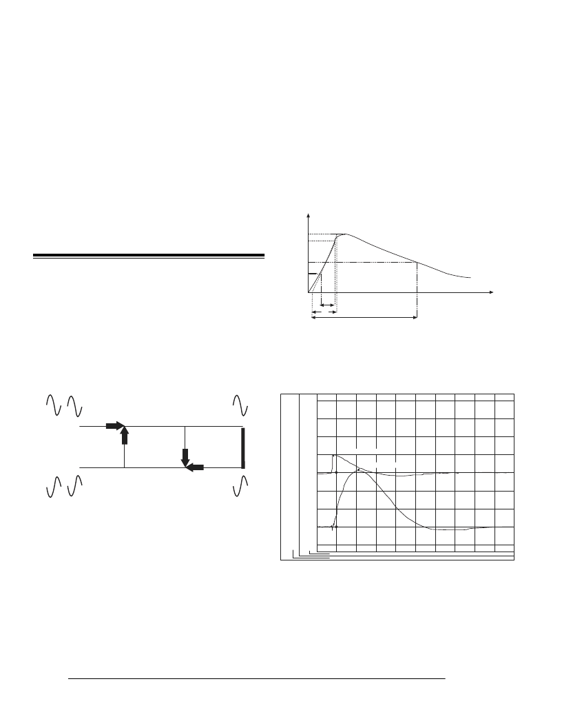
Quarter Wave Stub Tuners
These devices are three port coaxial connectors. The
third port extending from the main through path is
terminated in a short circuit at a pre-determined distance
calculated to be exactly one quarter wavelength at the
desired center frequency (see graph).
Unlike surge protectors, this design eliminates
concerns about residual pulse, sparkover voltage and
residual voltage ensuring greater protection for sensitive
electronic equipment. As opposed to surge protectors,
stub tuners will absorb lightning strikes without need
for replacing components. These devices yield very low
VSWR and feature high attenuation within a relatively
narrow pass-band (+/ - 70 MHz) but are application
specific. Stub tuners also pass energy in bands that are
harmonically related to the fundamental center
frequency. The graphs below show a typical test impulse
and the response of a stub tuner.
li
Vi
Vr
lr
0.3
1.0
1.9
0.5
0
V
T1 = 1.67T
T2
T
01
T1
t
32V
kA
24V
kA
16V
kA
81.V
kA
0.0
uV
47kA
-81V
31kA
-16V
15kA
-24V
5A
-32V
-1kA
01/16/96 14:07:02
-640.0nS, 80.033280 V
10.98uS, 49.45920kA
0.0nS
20.00uS
40.00uS
60.00uS
80.00uS
λ
/4 SHORTING STUB BASICS
TYPICAL TEST IMPULSE
TYPICAL
λ
/4 TEST RESPONSE
相關(guān)PDF資料 |
PDF描述 |
|---|---|
| ID221205 | TRANSISTOR | IGBT POWER MODULE | HALF BRIDGE | 1.2KV V(BR)CES | 50A I(C) |
| ID221210 | TRANSISTOR | IGBT POWER MODULE | HALF BRIDGE | 1.2KV V(BR)CES | 100A I(C) |
| ID221275 | TRANSISTOR | IGBT POWER MODULE | HALF BRIDGE | 1.2KV V(BR)CES | 75A I(C) |
| ID2212A2 | TRANSISTOR | IGBT POWER MODULE | HALF BRIDGE | 600V V(BR)CES | 50A I(C) |
| ID221K05 | TRANSISTOR | IGBT POWER MODULE | HALF BRIDGE | 1KV V(BR)CES | 50A I(C) |
相關(guān)代理商/技術(shù)參數(shù) |
參數(shù)描述 |
|---|---|
| ID2010 | 制造商:未知廠家 制造商全稱:未知廠家 功能描述:OSX(MCX) Microminiature Snap-On Connectors Series |
| ID2011 | 制造商:M/A-COM Technology Solutions 功能描述:RF COAXIAL LIGHTNING & EMP PROTECTION DEVICES - Bulk |
| ID2012 | 制造商:M/A-COM Technology Solutions 功能描述:LIGHTNING PROTECTION APPLICATION NOTE - Bulk |
| ID2016 | 制造商:M/A-COM Technology Solutions 功能描述:OSMT INTERCONNECT SYSTEM SURFACE MOUNT COAXIAL CONNECTORS - Bulk |
| ID202 | 制造商:Microsemi Corporation 功能描述:ID202 - Bulk |
發(fā)布緊急采購,3分鐘左右您將得到回復(fù)。