- 您現(xiàn)在的位置:買賣IC網(wǎng) > PDF目錄377427 > IDT72T20108L10BB (INTEGRATED DEVICE TECHNOLOGY INC) 2.5 VOLT HIGH-SPEED TeraSync⑩ DDR/SDR FIFO 20-BIT/10-BIT CONFIGURATION PDF資料下載
參數(shù)資料
| 型號(hào): | IDT72T20108L10BB |
| 廠商: | INTEGRATED DEVICE TECHNOLOGY INC |
| 元件分類: | DRAM |
| 英文描述: | 2.5 VOLT HIGH-SPEED TeraSync⑩ DDR/SDR FIFO 20-BIT/10-BIT CONFIGURATION |
| 中文描述: | 64K X 20 OTHER FIFO, 4.5 ns, PBGA208 |
| 封裝: | 17 X 17 MM, 1 MM PITCH, PLASTIC, BGA-208 |
| 文件頁數(shù): | 45/51頁 |
| 文件大小: | 496K |
| 代理商: | IDT72T20108L10BB |
第1頁第2頁第3頁第4頁第5頁第6頁第7頁第8頁第9頁第10頁第11頁第12頁第13頁第14頁第15頁第16頁第17頁第18頁第19頁第20頁第21頁第22頁第23頁第24頁第25頁第26頁第27頁第28頁第29頁第30頁第31頁第32頁第33頁第34頁第35頁第36頁第37頁第38頁第39頁第40頁第41頁第42頁第43頁第44頁當(dāng)前第45頁第46頁第47頁第48頁第49頁第50頁第51頁
45
COMMERCIAL AND INDUSTRIAL
TEMPERATURE RANGES
IDT72T2098/108/118/128 2.5V HIGH-SPEED TeraSync DDR/SDR FIFO 20-BIT/10-BIT CONFIGURATIONS
32K x 20/64K x 10, 64K x 20/128K x 10, 128K x 20/256K x 10, 256K x 20/512K x 10
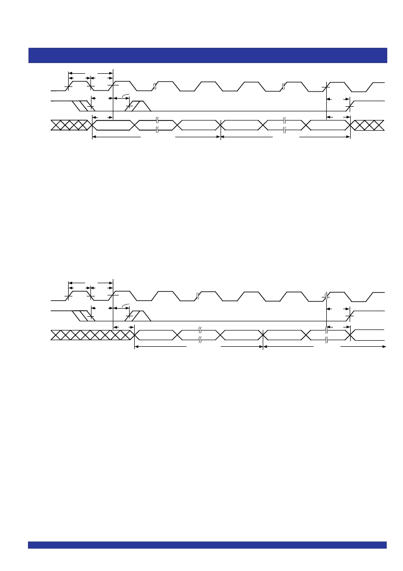
Figure 25. Loading of Programmable Flag Registers (IDT Standard and FWFT Modes)
NOTE:
1. In SDR mode, X = 16 for the IDT72T2098, X = 17 for the IDT72T20108, X = 18 for the IDT72T20118, X = 19 for the IDT72T20128 for X10 mode. X = 15 for the IDT72T2098,
X = 16 for the IDT72T20108, X = 17 for the IDT72T20118, X = 18 for the IDT72T20128 for all other modes.
2. In DDR mode, X = 15 for the IDT72T2098, X = 16 for the IDT72T20108, X = 17 for the IDT72T20118, X = 18 for the IDT72T20128 for X10 to X10 mode. X = 14 for the IDT72T2098,
X = 15 for the IDT72T20108, X = 16 for the IDT72T20118, X = 17 for the IDT 72T20128 for all other modes.
SCLK
SEN
SI
5996 drw28
EMPTY OFFSET
FULL OFFSET
BIT X
(1)
t
SENS
t
SDS
t
SENH
BIT X
(1)
BIT 1
t
ENH
t
SDH
t
SCLK
t
SCKH
t
SCKL
BIT 1
Figure 26. Reading of Programmable Flag Registers (IDT Standard and FWFT Modes)
NOTE:
1. In SDR mode, X = 15 for the IDT72T2098, X = 17 for the IDT72T20108, X = 18 for the IDT72T20118, X = 19 for the IDT72T20128 for X10 mode. X = 15 for the IDT72T2098,
X = 16 for the IDT72T20108, X = 17 for the IDT20118, X = 18 for the IDT72T20128 for all other modes.
2. In DDR mode, X = 15 for the IDT72T2098, X = 16 for the IDT72T20108, X = 17 for the IDT72T20118, X = 18 for the IDT20128, for X10 to X10 mode. X = 14 for the IDT72T72098,
X = 15 for the IDT72T20108, X = 16 for the IDT72T20118, X = 17 for the IDT72T20128 for all other modes.
3. Offset register values are always read starting fromthe first location in the offset register upon initiating
SREN
.
SCLK
SREN
SO
5996 drw29
BIT 0
EMPTY OFFSET
FULL OFFSET
BIT X
(1)
t
SENS
t
SOA
t
SENH
BIT X
(1)
t
ENH
t
SOA
t
SCLK
t
SCKH
t
SCKL
BIT 0
發(fā)布緊急采購,3分鐘左右您將得到回復(fù)。