- 您現(xiàn)在的位置:買賣IC網 > PDF目錄67720 > IMISG570CYB (CYPRESS SEMICONDUCTOR CORP) PROC SPECIFIC CLOCK GENERATOR, PDSO48 PDF資料下載
參數資料
| 型號: | IMISG570CYB |
| 廠商: | CYPRESS SEMICONDUCTOR CORP |
| 元件分類: | 時鐘產生/分配 |
| 英文描述: | PROC SPECIFIC CLOCK GENERATOR, PDSO48 |
| 封裝: | SSOP-48 |
| 文件頁數: | 8/14頁 |
| 文件大?。?/td> | 176K |
| 代理商: | IMISG570CYB |
SG570
I
2C Frequency Clock Generator w/ EMI Reduction Spread Spectrum Technology
for Pentium Processor Based Designs.
Preliminary
INTERNATIONAL MICROCIRCUITS, INC. 525 LOS COCHES ST.
Rev.1.1
3/23/98
MILPITAS, CA 95035. TEL: 408-263-6300. FAX 408-263-6571
Page 3 of 14
POWER MANAGEMENT FUNCTIONS
All clocks can be individually enabled or stopped via the 2-wire control interface. All clocks are stopped in the low
state. All clocks maintain a valid high period on transitions from running to stopped and on transitions from stopped to
running when the chip was not powered down. On power up, the VCOs will stabilize to the correct pulse widths within
about 0.2 mS. The CPU, SDRAM, and PCI clocks transition between running and stopped by waiting for one positive
edge on PCICLK_F followed by a negative edge on the clock of interest, after which high levels of the output are either
enabled or disabled.
When MODE=0, pins 26 and 27 are inputs PCI_STOP# and CPU_STOP# respectively (when MODE=1, these
functions are not available). A particular output is enabled only when both the serial interface and these pins indicate
that it should be enabled. The IMISG570 clocks may be disabled according to the following table in order to reduce
power consumption. All clocks are stopped in the low state. All clocks maintain a valid high period on transitions from
running to stopped. On low to high transitions of PWR_DWN#, external circuitry should allow 0.2 mS for the VCOs to
stabilize prior to assuming the clock periods are correct. The CPU and PCI clocks transition between running and
stopped by waiting for one positive edge on PCICLK_F followed by a negative edge on the clock of interest, after which
high levels of the output are either enabled or disabled.
CPU_STOP#
PCI_STOP#
PWR_DWN#
CPUCLK
PCICLK
OTHER CLKs
XTAL & VCOs
X
0
LOW
OFF
0
1
LOW
RUNNING
0
1
LOW
33/30 MHZ
RUNNING
1
0
1
66/60 MHZ
LOW
RUNNING
1
66/60 MHZ
33/30 MHZ
RUNNING
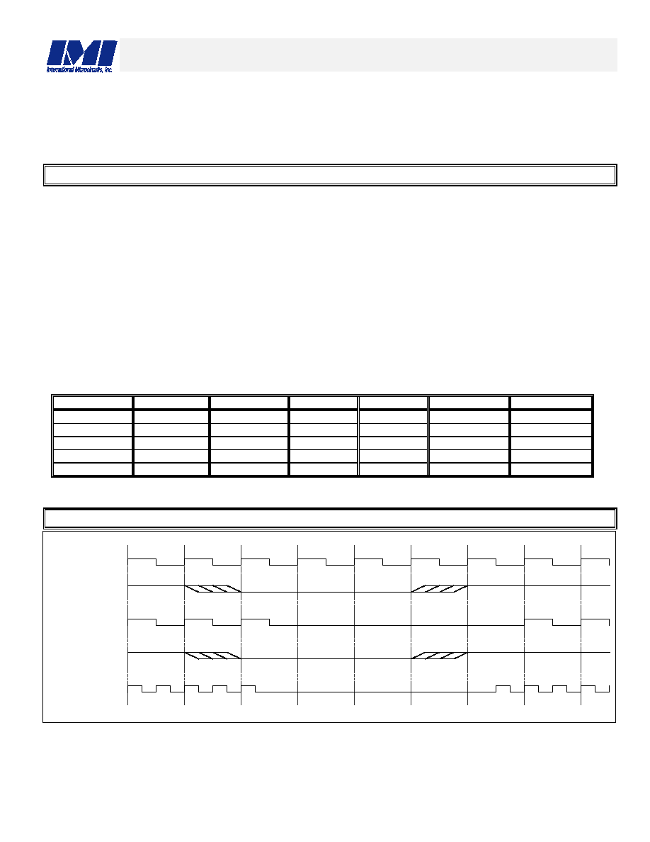
POWER MANAGEMENT TIMING
PCICLK_F
PCI_STOP#
PCICLK(0:5)
CPU_STOP#
CPUCLK(0:3)
相關PDF資料 |
PDF描述 |
|---|---|
| IMISG570CYB | PROC SPECIFIC CLOCK GENERATOR, PDSO48 |
| IMISM532AXB | OTHER CLOCK GENERATOR, PDSO16 |
| IMSA113-J20S | ACTIVE DELAY LINE, PQCC44 |
| IMSB419-4 | SPECIALTY MICROPROCESSOR CIRCUIT, XMA16 |
| IMSC011-E20S | 1 CHANNEL(S), 20M bps, SERIAL COMM CONTROLLER, PDSO28 |
相關代理商/技術參數 |
參數描述 |
|---|---|
| IMISG571DTB | 制造商:未知廠家 制造商全稱:未知廠家 功能描述:CPU System Clock Generator |
| IMISG571DYB | 制造商:未知廠家 制造商全稱:未知廠家 功能描述:CPU System Clock Generator |
| IMISG577CYB | 制造商:未知廠家 制造商全稱:未知廠家 功能描述:CPU System Clock Generator |
| IMISG745BYB | 制造商:未知廠家 制造商全稱:未知廠家 功能描述:CPU System Clock Generator |
| IMISG748CYB | 制造商:未知廠家 制造商全稱:未知廠家 功能描述:CPU System Clock Generator |
發(fā)布緊急采購,3分鐘左右您將得到回復。