- 您現(xiàn)在的位置:買賣IC網(wǎng) > PDF目錄360861 > INA104 (Texas Instruments, Inc.) Very-High Accuracy Instrumentation Amplifier(非常高精度的儀用放大器) PDF資料下載
參數(shù)資料
| 型號(hào): | INA104 |
| 廠商: | Texas Instruments, Inc. |
| 元件分類: | 運(yùn)動(dòng)控制電子 |
| 英文描述: | Very-High Accuracy Instrumentation Amplifier(非常高精度的儀用放大器) |
| 中文描述: | 甚高精度儀表放大器(非常高精度的儀用放大器) |
| 文件頁(yè)數(shù): | 9/11頁(yè) |
| 文件大?。?/td> | 132K |
| 代理商: | INA104 |
9
INA104
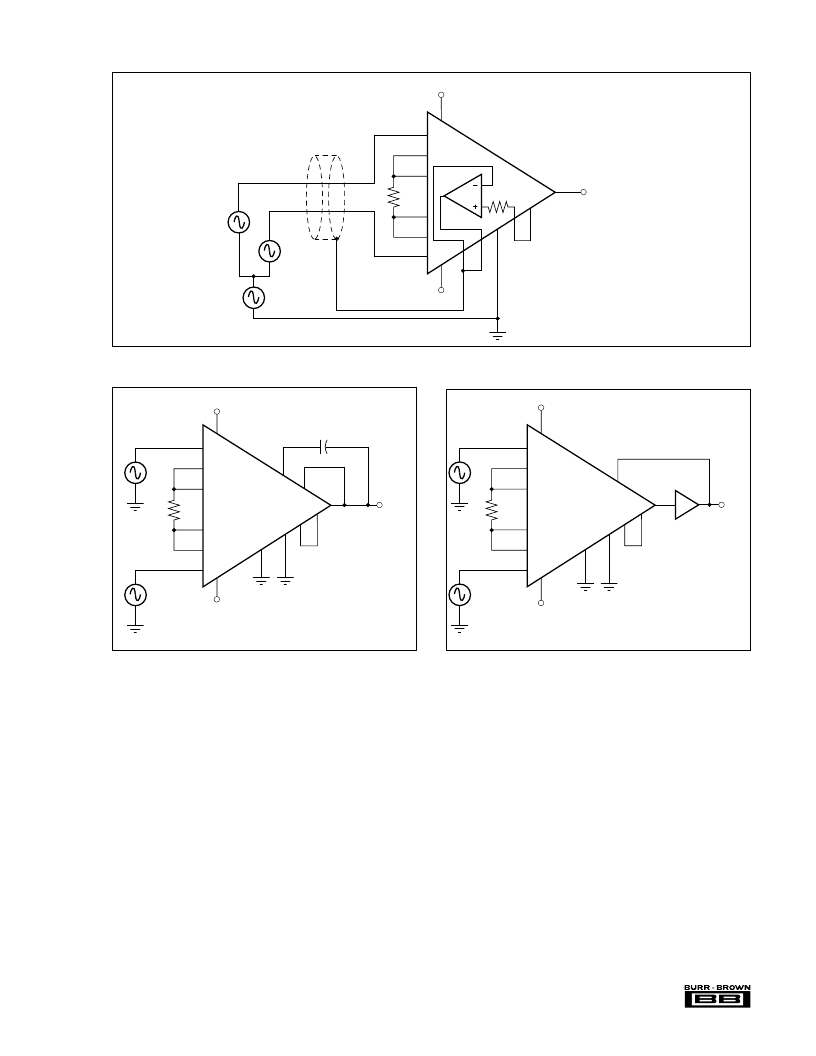
FIGURE 5. Use of Guard Drive.
FIGURE 7. Output Power Boosting.
FIGURE 6. Active Low-Pass Filtering.
to the low values of R
G
required (R
G
< 40
for (1 + 40k/R
G
)
> 1000). Note, however, that accuracy can degrade due to
high amplification of offset, drift, and noise errors.
Output offsetting (“zero suppression” or “zero elevation”)
may be more easily accomplished with the INA104 than
with most other IC instrumentation amplifiers as shown in
Figure 4. The use of the extra internal op amp, A
4
, means
that CMR of the instrumentation amp is not disturbed, and
that a convenient value of variable resistor can be used. The
circuit shown in Figure 2 can also be used to achieve the
desired offsetting by scaling the resistors R
1
and R
2
. A low
impedance path from pin 6 to Common should be provided
to achieve the high CMR specified. Resistance above 0.1
will cause the CMR to fall below 106dB.
Amplifier A
4
also allows active low-pass filtering to be
implemented conveniently with a single capacitor. Filtering
can be used for noise reduction or band-limiting of the
output signal as shown in Figure 6.
The common-mode voltage from the 26k
resistors in the
input section appears at pin 4. Figure 5 shows how this
voltage can be used to drive the shield of the input cable.
Since the cable is driven at the common-mode voltage, the
effects of distributed capacitance is reduced and the AC
system common-mode rejection may be improved. Ampli-
fier A
4
buffers the CMV at pin 4 from the input cable.
Some typical application circuits are shown in Figures 9
through 11.
3
12
10
6
7
4
8
13
17
18
14
5
1
2
INA104
5k
R
G
E
OUT
E
2
E
CM
E
1
+V
CC
–V
CC
E
OUT
= [E
2
– E
1
+ (E
CM
/CMRR)](1 + 40k/R
G
)
(1)
CMV Sense
NOTE: Internal Op Amp, A
4
, or External Amp (OPA27 or equivalent).
Shield
–In
+In
3
7
8
9
6
10
13
11
12
17
18
14
5
1
2
INA104
R
G
E
OUT
E
1
(f)
E
2
(f)
+V
CC
–V
CC
(1)
NOTE: (1) A
4
inverts, see Figure 3.
E
OUT
= (E
1
– E
2
)[1 + (40k/R
G
)][1/(1 + 2
π
f 10
4
x C
F
)]
C
F
f
= (1/2
π
C
10
4
)Hz
C
F
in farads used with A
4
.
3
7
8
9
6
10
13
11
17
18
14
5
1
2
INA104
R
G
E
OUT
E
1
E
2
+V
CC
–V
CC
(1)
NOTE: (1) A
4
inverts. See Figure 3.
Current Booster
3553 or BUF634
Used with A
4
相關(guān)PDF資料 |
PDF描述 |
|---|---|
| INA105KP-BI | Single Differential Amplifier |
| INA105KU-BI | Single Differential Amplifier |
| INA106U | Single Differential Amplifier |
| INA105 | Precision Unity Gain DIFFERENTIAL AMPLIFIER |
| INA105AM | Precision Unity Gain DIFFERENTIAL AMPLIFIER |
相關(guān)代理商/技術(shù)參數(shù) |
參數(shù)描述 |
|---|---|
| INA104AM | 制造商:BB 制造商全稱:BB 功能描述:Very-High Accuracy INSTRUMENTATION AMPLIFIER |
| IN-A-104B-H/MS-PC-212 | 制造商:Hirose 功能描述:901-1090-9-00 EACH 制造商:Hirose 功能描述:IN-A-104B-H/MS-PC-212 |
| INA104BM | 制造商:BB 制造商全稱:BB 功能描述:Very-High Accuracy INSTRUMENTATION AMPLIFIER |
| INA104CM | 制造商:BB 制造商全稱:BB 功能描述:Very-High Accuracy INSTRUMENTATION AMPLIFIER |
| INA104SM | 制造商:BB 制造商全稱:BB 功能描述:Very-High Accuracy INSTRUMENTATION AMPLIFIER |
發(fā)布緊急采購(gòu),3分鐘左右您將得到回復(fù)。