- 您現(xiàn)在的位置:買賣IC網(wǎng) > PDF目錄360889 > IP1526D Analog IC PDF資料下載
參數(shù)資料
| 型號: | IP1526D |
| 英文描述: | Analog IC |
| 中文描述: | 模擬IC |
| 文件頁數(shù): | 2/6頁 |
| 文件大?。?/td> | 72K |
| 代理商: | IP1526D |

LAB
SEME
IP1524 SERIES
Semelab plc.
Telephone (01455) 556565. Telex: 341927. Fax (01455) 552612.
Prelim. 3/95
V
R
C
+5V TO ALL
INTERNAL CIRCUITRY
INV.
INPUT
N.I.
INPUT
GND
ERROR
AMP
REFERENCE
REGULATOR
OSCILLATOR
OSCILLATOR
OUTPUT
3
FLIP
FLOP
COMPARATOR
+5V
NOR
NOR
SHUTDOWN
C
E
C
E
+5V
C.L.
(SUBSTRATE)
COMPENSATION
+SENSE
–SENSE
+5V
4
9
5
1
2
8
10
IN
T
T
15
6
7
A
A
B
B
12
11
13
14
16
1k
10k
+8 to +40V
0 to +40V
+1.8 to +3.4V
0 to 100mA
0 to 20mA
30
μ
A to 2mA
50Hz to 500kHz
1.8k
to 100k
1nF to 0.1
μ
F
–55 to +125°C
-25 to +85°C
0 to +70°C
RECOMMENDED OPERATING CONDITIONS
V
IN
Input Voltage
Collector Voltage
Error Amp Common Mode Range
Output Current
Reference Load Current
Oscillator Charging Current
Oscillator Frequency Range
R
T
Oscillator Timing Resistor
C
T
Oscillator Timing Capacitor
T
AMB
Operating Ambient Temperature Range
DESCRIPTION
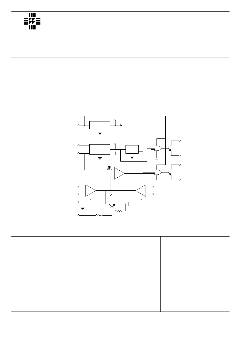
The IP1524 series of PWM switching regulator control circuits contains all the functions required to implement single-
ended or push-pull switching regulators. Included are voltage reference, error amplifer, oscillator, PWM comparator,
output drivers, current limiting and shutdown circuitry.
Although functionally indentical to the SG1524 series, SEMELAB has incorporated several improvements to the IP1524
allowing tighter and more complete specification of electrical performance.
BLOCK DIAGRAM
(each transistor)
IP1524
IP2524
IP3524
相關(guān)PDF資料 |
PDF描述 |
|---|---|
| IP1526J | Voltage-Mode SMPS Controller |
| IP1526N | Analog IC |
| IP3526D-18 | Analog IC |
| IP1527J | Analog IC |
| IP2524BD | Analog IC |
相關(guān)代理商/技術(shù)參數(shù) |
參數(shù)描述 |
|---|---|
| IP1526J | 制造商:未知廠家 制造商全稱:未知廠家 功能描述:Voltage-Mode SMPS Controller |
| IP1526J/883B | 制造商:未知廠家 制造商全稱:未知廠家 功能描述:Voltage-Mode SMPS Controller |
| IP1526N | 制造商:未知廠家 制造商全稱:未知廠家 功能描述:Analog IC |
| IP1527A | 制造商:SEME-LAB 制造商全稱:Seme LAB 功能描述:REGULATING PULSE WIDTH MODULATORS |
| IP1527AJ | 制造商:未知廠家 制造商全稱:未知廠家 功能描述:Analog IC |
發(fā)布緊急采購,3分鐘左右您將得到回復(fù)。