- 您現(xiàn)在的位置:買賣IC網(wǎng) > PDF目錄377577 > IS80LV31-40PQ (INTEGRATED SILICON SOLUTION INC) CMOS SINGLE CHIP LOW VOLTAGE 8-BIT MICROCONTROLLER PDF資料下載
參數(shù)資料
| 型號: | IS80LV31-40PQ |
| 廠商: | INTEGRATED SILICON SOLUTION INC |
| 元件分類: | 微控制器/微處理器 |
| 英文描述: | CMOS SINGLE CHIP LOW VOLTAGE 8-BIT MICROCONTROLLER |
| 中文描述: | 8-BIT, 40 MHz, MICROCONTROLLER, PQFP44 |
| 封裝: | PLASTIC, QFP-44 |
| 文件頁數(shù): | 14/43頁 |
| 文件大小: | 339K |
| 代理商: | IS80LV31-40PQ |
第1頁第2頁第3頁第4頁第5頁第6頁第7頁第8頁第9頁第10頁第11頁第12頁第13頁當前第14頁第15頁第16頁第17頁第18頁第19頁第20頁第21頁第22頁第23頁第24頁第25頁第26頁第27頁第28頁第29頁第30頁第31頁第32頁第33頁第34頁第35頁第36頁第37頁第38頁第39頁第40頁第41頁第42頁第43頁
IS80LV51
IS80LV31
14
Integrated Silicon Solution, Inc.
ADVANCE INFORMATION
MC018-0A
10/01/98
ISSI
TIMER/COUNTERS
The IS80LV51/31 has two 16-bit Timer/Counter registers:
Timer 0 and Timer 1. Both can be configured to operate
either as Timers or event Counters.
As a Timer, the register is incremented every machine
cycle. Thus, the register counts machine cycles. Since a
machine cycle consists of 12 oscillator periods, the count
rate is 1/12 of the oscillator frequency.
As a Counter, the register is incremented in response to a
1-to-0 transition at its corresponding external input pin, T0
and T1. The external input is sampled during S5P2 of
every machine cycle. When the samples show a high in
one cycle and a low in the next cycle, the count is
incremented. The new count value appears in the register
during S3P1 of the cycle following the one in which the
transition was detected. Since two machine cycles (24
oscillator periods) are required to recognize a 1-to-0
transition, the maximum count rate is 1/24 of the oscillator
frequency. There are no restrictions on the duty cycle of
the external input signal, but it should be held for at least
one full machine cycle to ensure that a given level is
sampled at least once before it changes.
In addition to the Timer or Counter functions, Timer 0 and
Timer 1 have four operating modes: (13-bit timer, 16-bit
timer, 8-bit auto-reload, split timer).
Timer 0 and Timer 1
Timer/Counters 0 and 1 are present in both the
IS80LV51/31 and IS80LV52/32. The Timer or Counter
function is selected by control bits C/
T
in the Special
Function Regiser TMOD. These two Timer/Counters have
four operating modes, which are selected by bit pairs (M1,
M0) in TMOD. Modes 0, 1, and 2 are the same for both
Timer/Counters, but Mode 3 is different. The four modes
are described in the following sections.
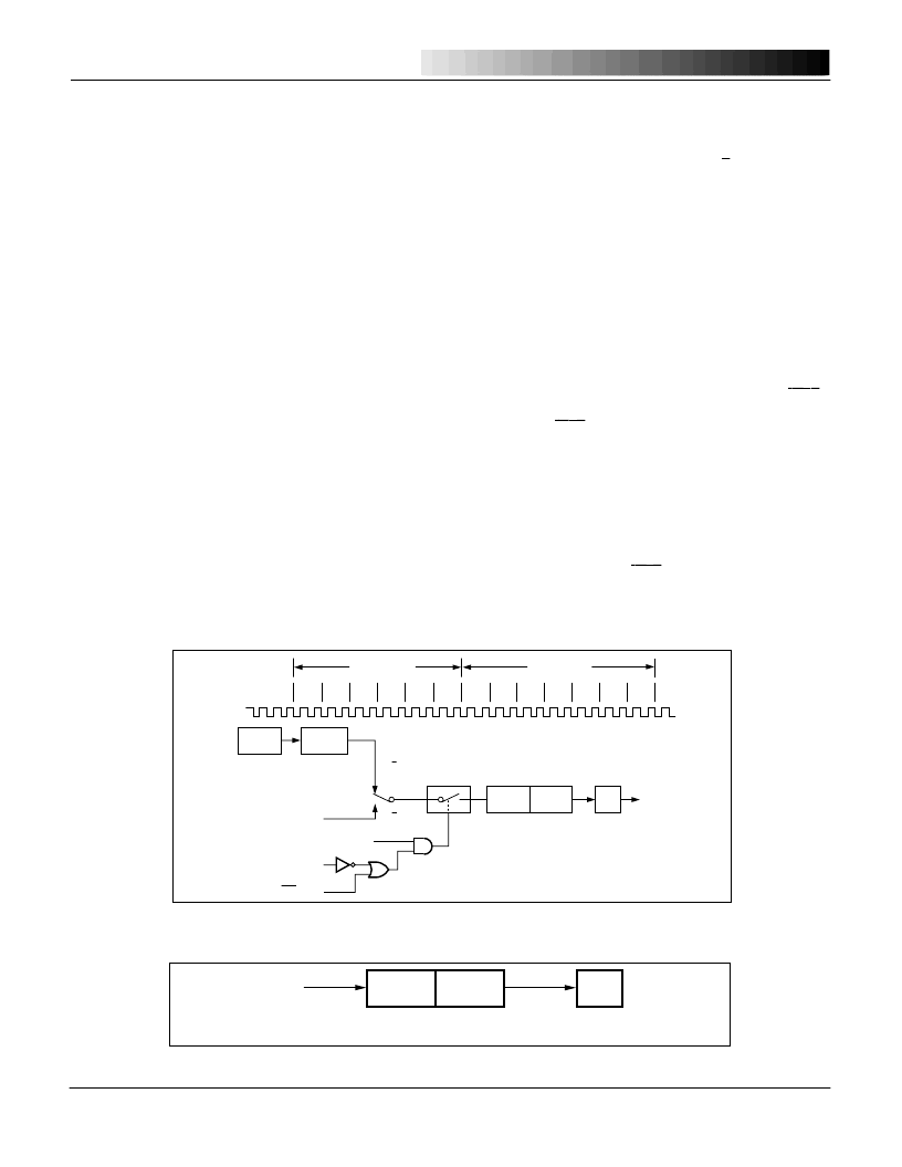
Mode 0:
Both Timers in Mode 0 are 8-bit Counters with a divide-by-
32
prescaler. Figure 8 shows the Mode 0 operation as it
applies to Timer 1.
In this mode, the Timer register is configured as a 13-bit
register. As the count rolls over from all 1s to all 0s, it sets
the Timer interrupt flag TF1. The counted input is enabled
to the Timer when TR1 = 1 and either GATE = 0 or
INT1
=
1. Setting GATE = 1 allows the Timer to be controlled by
external input
INT1
, to facilitate pulse width measurements.
TR1 is a control bit in the Special Function Register TCON.
Gate is in TMOD.
The 13-bit register consists of all eight bits of TH1 and the
lower five bits of TL1. The upper three bits of TL1 are
indeterminate and should be ignored. Setting the run flag
(TR1) does not clear the registers.
Mode 0 operation is the same for Timer 0 as for Timer 1,
except that TR0, TF0 and
INT0
replace the corresponding
Timer 1 signals in Figure 8. There are two different GATE
bits, one for Timer 1 (TMOD.7) and one for Timer 0
(TMOD.3).
TIMER
CLOCK
TL1
(8 BITS)
TH1
(8 BITS)
TF1
OVERFLOW
FLAG
Figure 9. Timer/Counter 1 Mode 1: 16-Bit Counter
DIVIDE 12
OSC
OSC
(XTAL2)
(5TL1
(8TH1
TF1
CONTROL
C/T = 0
C/T = 1
GATE
INT1 PIN
TR1
T1 PIN
INTERRUPT
P1
S1
S2
S3
ONE MACHINE
CYCLE
ONE MACHINE
CYCLE
S3
S4
S4
S5
S6
S1
S2
S5
S6
S1
P2
P1 P2 P1 P2 P1 P2 P1 P2 P1 P2 P1 P2 P1 P2 P1 P2 P1P2 P1P2 P1 P2
P1 P2
Figure 8. Timer/Counter 1 Mode 0: 13-Bit Counter
相關(guān)PDF資料 |
PDF描述 |
|---|---|
| IS80LV31-40PQI | CMOS SINGLE CHIP LOW VOLTAGE 8-BIT MICROCONTROLLER |
| IS80LV31-40W | CMOS SINGLE CHIP LOW VOLTAGE 8-BIT MICROCONTROLLER |
| IS80LV31-40WI | CMOS SINGLE CHIP LOW VOLTAGE 8-BIT MICROCONTROLLER |
| IS80LV51-24PL | CMOS SINGLE CHIP LOW VOLTAGE 8-BIT MICROCONTROLLER |
| IS80LV51-24PLI | CMOS SINGLE CHIP LOW VOLTAGE 8-BIT MICROCONTROLLER |
相關(guān)代理商/技術(shù)參數(shù) |
參數(shù)描述 |
|---|---|
| IS80LV31-40PQI | 制造商:ISSI 制造商全稱:Integrated Silicon Solution, Inc 功能描述:CMOS SINGLE CHIP LOW VOLTAGE 8-BIT MICROCONTROLLER |
| IS80LV31-40W | 制造商:ISSI 制造商全稱:Integrated Silicon Solution, Inc 功能描述:CMOS SINGLE CHIP LOW VOLTAGE 8-BIT MICROCONTROLLER |
| IS80LV31-40WI | 制造商:ISSI 制造商全稱:Integrated Silicon Solution, Inc 功能描述:CMOS SINGLE CHIP LOW VOLTAGE 8-BIT MICROCONTROLLER |
| IS80LV32 | 制造商:ISSI 制造商全稱:Integrated Silicon Solution, Inc 功能描述:CMOS SINGLE CHIP LOW VOLTAGE 8-BIT MICROCONTROLLER |
| IS80LV32-24PL | 制造商:ISSI 制造商全稱:Integrated Silicon Solution, Inc 功能描述:CMOS SINGLE CHIP LOW VOLTAGE 8-BIT MICROCONTROLLER |
發(fā)布緊急采購,3分鐘左右您將得到回復(fù)。