- 您現(xiàn)在的位置:買賣IC網(wǎng) > PDF目錄9266 > ISL22512WFRU10Z-TK (Intersil)IC POT DGTL PB 16TP LN LP 10TQFN PDF資料下載
參數(shù)資料
| 型號(hào): | ISL22512WFRU10Z-TK |
| 廠商: | Intersil |
| 文件頁(yè)數(shù): | 4/11頁(yè) |
| 文件大?。?/td> | 0K |
| 描述: | IC POT DGTL PB 16TP LN LP 10TQFN |
| 標(biāo)準(zhǔn)包裝: | 1,000 |
| 系列: | XDCP™ |
| 接片: | 16 |
| 電阻(歐姆): | 10k |
| 電路數(shù): | 1 |
| 溫度系數(shù): | 標(biāo)準(zhǔn)值 ±80 ppm/°C |
| 存儲(chǔ)器類型: | 非易失 |
| 接口: | 2 線按鈕 |
| 電源電壓: | 2.7 V ~ 5.5 V |
| 工作溫度: | -40°C ~ 125°C |
| 安裝類型: | 表面貼裝 |
| 封裝/外殼: | 10-UFQFN |
| 供應(yīng)商設(shè)備封裝: | 10-UTQFN(2.1x1.6) |
| 包裝: | 帶卷 (TR) |

2
FN6679.2
October 27, 2011
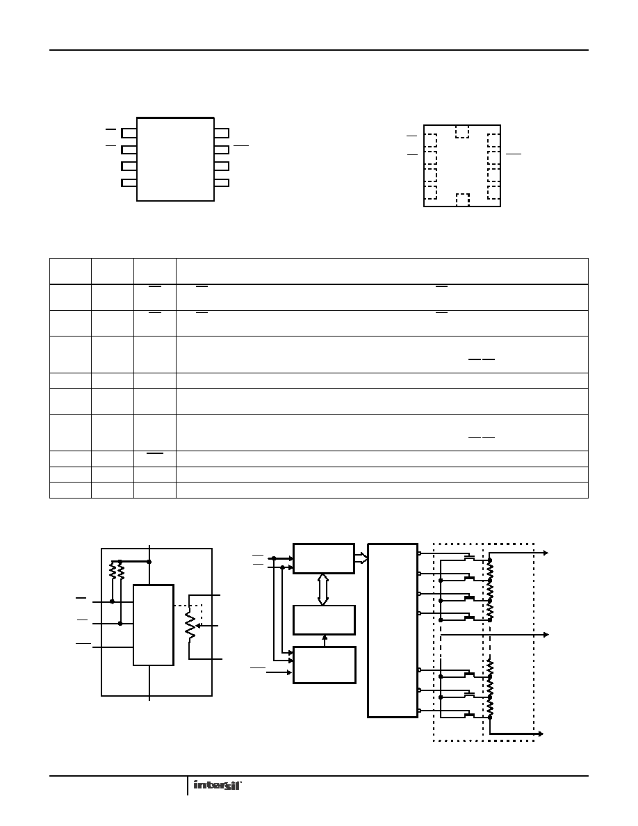
Block Diagrams
Pinouts
ISL22512
(8 LD SOIC)
TOP VIEW
ISL22512
(10 LD ΜTQFN)
TOP VIEW
VCC
ASE
PU
PD
RH
VSS
1
2
3
4
8
7
6
5
RL
RW
O
9
8
7
6
1
2
3
4
NC
VSS
ASE
RL
VCC
PU
RH
5
10
PD
O
RW
NC
Pin Descriptions
SOIC
PIN
TQFN
PIN
SYMBOL
BRIEF DESCRIPTION
11
PU
The PU is a falling-edge triggered input with internal pull-up. Toggling PU will move the wiper close to RH
terminal.
22
PD
The PD is a falling-edge triggered input with internal pull-up. Toggling PD will move the wiper close to RL
terminal.
3
RH
The RH and RL pins of the ISL22512 are equivalent to the fixed terminals of a mechanical potentiometer. The
minimum voltage is VSS and the maximum is VCC. The terminology of RH and RL references the relative
position of the terminal in relation to wiper movement direction selected by the PU/PD input.
44
VSS
Ground
5
6
RW
The RW pin is the wiper terminal of the potentiometer which is equivalent to the movable terminal of a
mechanical potentiometer.
6
7
RL
The RH and RL pins of the ISL22512 are equivalent to the fixed terminals of a mechanical potentiometer. The
minimum voltage is VSS and the maximum is VCC. The terminology of RH and RL references the relative
position of the terminal in relation to wiper movement direction selected by the PU/PD input.
7
8
ASE
Active low AUTOSTORE enable input or Manual Store active low input
89
VCC
Supply Voltage
5, 10
NC
No connection
4-BIT
UP/DOWN
COUNTER
4-BIT
NONVOLATILE
MEMORY
STORE AND
RECALL
CONTROL
CIRCUITRY
ONE
OF
DECODER
RESISTOR
ARRAY
RH
PU
PD
TRANSFER
GATES
THIRTY
RL
CONTROL
AND
MEMORY
PU
PD
VCC (SUPPLY VOLTAGE)
VSS (GROUND)
RH
GENERAL
DETAILED
0
1
2
28
29
30
31
TWO
RL
RW
ASE
ISL22512
相關(guān)PDF資料 |
PDF描述 |
|---|---|
| MS27474E22A55P | CONN RCPT 55POS JAM NUT W/PINS |
| MS27497E24B35PD | CONN RCPT 128POS WALL MNT W/PINS |
| VI-J6Y-MZ | CONVERTER MOD DC/DC 3.3V 16.5W |
| DS1004Z-4+ | IC DELAY LINE 5TAP 21NS 8-SOIC |
| VI-252-MX-B1 | CONVERTER MOD DC/DC 15V 75W |
相關(guān)代理商/技術(shù)參數(shù) |
參數(shù)描述 |
|---|---|
| ISL23315 | 制造商:INTERSIL 制造商全稱:Intersil Corporation 功能描述:Single, Low Voltage Digitally Controlled Potentiometer (XDCP?) |
| ISL23315_11 | 制造商:INTERSIL 制造商全稱:Intersil Corporation 功能描述:Single, Low Voltage Digitally Controlled Potentiometer |
| ISL23315TFRUZ-T7A | 功能描述:數(shù)字電位計(jì) IC 256 TAP VOLATILE I2C FL RNG INC DCP 21X16 RoHS:否 制造商:Maxim Integrated 電阻:200 Ohms 溫度系數(shù):35 PPM / C 容差:25 % POT 數(shù)量:Dual 每 POT 分接頭:256 弧刷存儲(chǔ)器:Volatile 緩沖刷: 數(shù)字接口:Serial (3-Wire, SPI) 描述/功能:Dual Volatile Low Voltage Linear Taper Digital Potentiometer 工作電源電壓:1.7 V to 5.5 V 電源電流:27 uA 最大工作溫度:+ 125 C 安裝風(fēng)格:SMD/SMT 封裝 / 箱體:TQFN-16 封裝:Reel |
| ISL23315TFRUZ-TK | 功能描述:數(shù)字電位計(jì) IC 256 TAP VOLATILE I2C FL RNG INC DCP 21X16 RoHS:否 制造商:Maxim Integrated 電阻:200 Ohms 溫度系數(shù):35 PPM / C 容差:25 % POT 數(shù)量:Dual 每 POT 分接頭:256 弧刷存儲(chǔ)器:Volatile 緩沖刷: 數(shù)字接口:Serial (3-Wire, SPI) 描述/功能:Dual Volatile Low Voltage Linear Taper Digital Potentiometer 工作電源電壓:1.7 V to 5.5 V 電源電流:27 uA 最大工作溫度:+ 125 C 安裝風(fēng)格:SMD/SMT 封裝 / 箱體:TQFN-16 封裝:Reel |
| ISL23315TFUZ | 功能描述:數(shù)字電位計(jì) IC 256 TAP VOLATILE I2C DL FL RNG DCP 10LD RoHS:否 制造商:Maxim Integrated 電阻:200 Ohms 溫度系數(shù):35 PPM / C 容差:25 % POT 數(shù)量:Dual 每 POT 分接頭:256 弧刷存儲(chǔ)器:Volatile 緩沖刷: 數(shù)字接口:Serial (3-Wire, SPI) 描述/功能:Dual Volatile Low Voltage Linear Taper Digital Potentiometer 工作電源電壓:1.7 V to 5.5 V 電源電流:27 uA 最大工作溫度:+ 125 C 安裝風(fēng)格:SMD/SMT 封裝 / 箱體:TQFN-16 封裝:Reel |
發(fā)布緊急采購(gòu),3分鐘左右您將得到回復(fù)。