- 您現(xiàn)在的位置:買賣IC網(wǎng) > PDF目錄383135 > ISL5585FCM (INTERSIL CORP) 3.3V Ringing SLIC Family for Voice Over Broadband VOB PDF資料下載
參數(shù)資料
| 型號(hào): | ISL5585FCM |
| 廠商: | INTERSIL CORP |
| 元件分類: | 模擬傳輸電路 |
| 英文描述: | 3.3V Ringing SLIC Family for Voice Over Broadband VOB |
| 中文描述: | TELECOM-SLIC, PQCC28 |
| 封裝: | PLASTIC, MS-018AB, LCC-28 |
| 文件頁數(shù): | 11/22頁 |
| 文件大?。?/td> | 425K |
| 代理商: | ISL5585FCM |
11
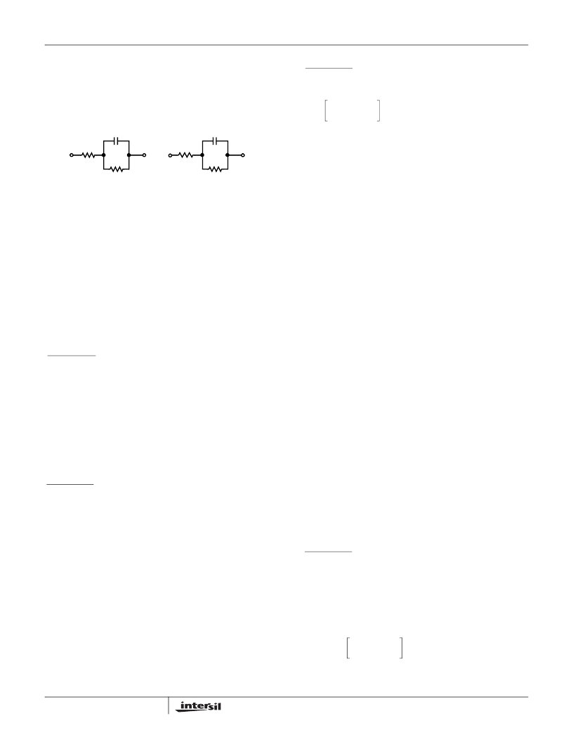
Complex Impedance Synthesis
Substituting the impedance programming resistor, R
S
, with a
complex programming network provides complex
impedance synthesis.
The reference designators in the programming network
match the evaluation board. The component R
S
has a
different design equation than the R
S
used for resistive
impedance synthesis. The design equations for each
component are provided below.
Substituting EQ 17 for VTX with AUX =0 and
I
M
= -V
2W
/Z
L
gives us EQ 26. Note: AUX input is not used.
Substitute EQ 17 into EQ 21
Substitute EQ 26 into EQ 27
Substitute Equation 19 for R
S
/8k in Equation 28.
Simplifying
Substitute Equation 30 into Equation 31 and combine terms
where:
V
IN
= The input voltage at the -IN pinthrough resistor R
IN
.
AUX = Auxiliary input of SLIC. Not used for AC gains.
V
SA
= An internal node voltage that is a function of the loop
current and the output of the Sense Amplifier.
I
X
= Internal current in the SLIC that is the difference between
the input receive current and the feedback current.
I
M
= The AC metallic current.
R
P
= A protection resistor (typical 49.9
).
R
S
= An external resistor/network for matching the line
impedance.
V
TR
= The tip to ring voltage at the output pins of the SLIC.
V
2W
= The tip to ring voltage including the voltage across the
protection resistors.
Z
L
= The line impedance.
Z
O
= The source impedance of the device.
4-Wire to 2-Wire Gain
4-wire to 2-wire gain across the ISL5585 is equal to the V
2W
divided by the input voltage V
IN
, reference Figure 4. The
receive gain is calculated using Equation 32.
Equation 33 expresses the receive gain (V
IN
to V
2W
) in
terms of network impedances. From Equation 21, the value
of R
S
was set to match the line impedance (Z
L
) to the
ISL5585 plus the protection resistors (Z
0
+ 2R
P
). This
results in a 4-wire to 2-wire gain equal to R
S
/R
IN
, as shown
in EQ. 33.
V
IN
2-Wire to 4-Wire Gain
The 2-wire to 4-wire gain is equal to V
TX
/E
G
with V
IN
= 0,
reference Figure 4.
Loop Equation
From Equation 30 with V
IN
= 0
Z
V
L
Substituting Equation 35 into Equation 34 and simplify.
FIGURE 5. COMPLEX PROGRAMMING NETWORK
2-WIRE
NETWORK
C
2
R
1
R
2
PROGRAMMING
NETWORK
C
Parallel
R
Series
R
Parallel
R
Series
133.3
R
1
2 R
P
(
)
–
(
)
×
=
(EQ. 22)
R
Parallel
133.3
R
2
×
=
(EQ. 23)
C
Parallel
C
2
133.3
=
(EQ. 24)
I
X
------------
+
V
----------
=
Node Equation
(EQ. 25)
at ISL5585 AUX input, Figure 4
I
X
V
----------
V
---------
R
S
IN
---------
–
V
30
L
-----------------
–
R
S
-----------
=
=
(EQ. 26)
I
X
R - V
TR
+ I
X
R = 0
Loop Equation
(EQ. 27)
at ISL5585 feed amplifiers and load.
V
TR
2V
IN
R
S
IN
---------
–
2V
30
L
---------------------
R
S
8k
-------
+
=
(EQ. 28)
V
TR
2V
IN
R
S
IN
---------
–
2V
30
L
---------------------
133.33Z
O
--------------------------
+
=
(EQ. 29)
V
TR
2V
IN
R
S
IN
---------
–
V
L
----------
Z
O
(
)
+
=
(EQ. 30)
V
2W
-I
M
2R
P
+ V
TR
= 0
Loop Equation
(EQ. 31)
at Tip/Ring interface
V
2W
Z
--------------------------------------
Z
L
2R
P
+
+
2V
IN
R
S
IN
---------
=
(EQ. 32)
G
4-2
=
-----------
= 2
R
S
IN
---------
Z
L
L
Z
O
+ 2
RP
-------+
2
Z
L
Z
L
-------+
R
S
IN
---------
=
=
(EQ. 33)
E
–
G
Z
L
I
M
2R
P
I
M
V
TR
–
+
+
0
=
(EQ. 34)
V
TR
--------------------
=
(EQ. 35)
E
G
V
2W
Z
--------------------------------------
2R
L
Z
O
+
+
–
=
(EQ. 36)
ISL5585
相關(guān)PDF資料 |
PDF描述 |
|---|---|
| ISL5585FCR | 3.3V Ringing SLIC Family for Voice Over Broadband VOB |
| ISL5586BIM | Low Power Ringing SLIC for Home Gateways |
| ISL5586FCM | Low Power Ringing SLIC for Home Gateways |
| ISL5586CIM | Low Power Ringing SLIC for Home Gateways |
| ISL5586DIM | Low Power Ringing SLIC for Home Gateways |
相關(guān)代理商/技術(shù)參數(shù) |
參數(shù)描述 |
|---|---|
| ISL5585FCMZ | 制造商:Intersil Corporation 功能描述:SLIC 1CH 53DB 45MA 3.3V/-18V/-24V/-28V 28PLCC - Rail/Tube 制造商:Intersil 功能描述:RINGING SLIC W/3 3V VCC 75V/53DB |
| ISL5585FCMZ-T | 制造商:Intersil Corporation 功能描述:SLIC 1CH 53DB 45MA 3.3V/-18V/-24V/-28V 28PLCC - Tape and Reel 制造商:Intersil 功能描述:RINGING SLIC W/3 3V VCC 75V/53DB |
| ISL5585FCR | 制造商:INTERSIL 制造商全稱:Intersil Corporation 功能描述:3.3V Ringing SLIC Family for Voice Over Broadband VOB |
| ISL5585FCR-TK | 功能描述:IC SLIC RINGING 3.3V VOB 32-QFN RoHS:否 類別:集成電路 (IC) >> 接口 - 電信 系列:- 產(chǎn)品培訓(xùn)模塊:Lead (SnPb) Finish for COTS 產(chǎn)品變化通告:Product Discontinuation 06/Feb/2012 標(biāo)準(zhǔn)包裝:750 系列:* |
| ISL5585FCRZ | 制造商:Intersil Corporation 功能描述: 制造商:Intersil Corporation 功能描述:Telecom Line Management ICs RINGING SLIC W/3 3V VCC 75V/53DB |
發(fā)布緊急采購(gòu),3分鐘左右您將得到回復(fù)。