- 您現(xiàn)在的位置:買賣IC網(wǎng) > PDF目錄383156 > ISL6557CB-T (INTERSIL CORP) Multi-Phase PWM Controller for Core-Voltage Regulation PDF資料下載
參數(shù)資料
| 型號(hào): | ISL6557CB-T |
| 廠商: | INTERSIL CORP |
| 元件分類: | 穩(wěn)壓器 |
| 英文描述: | Multi-Phase PWM Controller for Core-Voltage Regulation |
| 中文描述: | SWITCHING CONTROLLER, 1500 kHz SWITCHING FREQ-MAX, PDSO24 |
| 封裝: | PLASTIC, MS-013AD, SOIC-24 |
| 文件頁(yè)數(shù): | 14/17頁(yè) |
| 文件大小: | 532K |
| 代理商: | ISL6557CB-T |
第1頁(yè)第2頁(yè)第3頁(yè)第4頁(yè)第5頁(yè)第6頁(yè)第7頁(yè)第8頁(yè)第9頁(yè)第10頁(yè)第11頁(yè)第12頁(yè)第13頁(yè)當(dāng)前第14頁(yè)第15頁(yè)第16頁(yè)第17頁(yè)
14
The feedback resistor, R
FB
, has already been chosen as
outlined in
Load-Line Regulation Resistor
. Select a target
bandwidth for the compensated system, f
0
. The target
bandwidth must be large enough to assure adequate
transient performance, but smaller than 1/3 of the per-
channel switching frequency. The values of the
compensation components depend on the relationships of f
0
to the L-C pole frequency and the ESR zero frequency. For
each of the three cases defined below, there is a separate
set of equations for the compensation components.
In Equations 20, L is the per-channel filter inductance
divided by the number of active channels; C is the sum total
of all output capacitors; ESR is the equivalent-series
resistance of the bulk output-filter capacitance; and V
PP
is
the peak-to-peak sawtooth signal amplitude as described in
Figure 5 and
Electrical Specifications
.
Once selected, the compensation values in Equations 20
assure a stable converter with reasonable transient
performance. In most cases, transient performance can be
improved by making adjustments to R
C
. Slowly increase the
value of R
C
while observing the transient performance on an
oscilloscope until no further improvement is noted. Normally,
C
C
will not need adjustment. Keep the value of C
C
from
Equations 20 unless some performance issue is noted.
The optional capacitor C
2
, is sometimes needed to bypass
noise away from the PWM comparator (see Figure 5). Keep
a position available for C
2
, and be prepared to install a high-
frequency capacitor of between 22pF and 150pF in case any
jitter problem is noted.
COMPENSATION WITHOUT LOAD-LINE REGULATION
The non load-line regulated converter is accurately modeled
as a voltage-mode regulator with two poles at the L-C
resonant frequency and a zero at the ESR frequency. A type
III controller, as shown in Figure 13, provides the necessary
compensation.
The first step is to choose the desired bandwidth, f
0
, of the
compensated system. Choose a frequency high enough to
assure adequate transient performance but not higher than
1/3 of the switching frequency. The type-III compensator has
an extra high-frequency pole, f
HF
. This pole can be used for
added noise rejection or to assure adequate attenuation at
the error-amplifier high-order pole and zero frequencies. A
u
le is to chose f
HF
= 1
0f
0
, but it can be higher
if desired. Choosing f
HF
to be lower than 1
0
f
0
can cause
problems with too much phase shift below the system
bandwidth.
In the solutions to the compensation equations, there is a
single degree of freedom. For the solutions presented in
Equations 21, R
FB
is selected arbitrarily. The remaining
compensation components are then selected according to
Equations 21.
2
π
LC
-------------------
f
0
>
R
C
R
FB
2
π
f
V
LC
IN
0.75V
PP
FB
f
0
-----------------------------------
=
C
C
------------------------------------
=
Case 1:
2
π
LC
-------------------
f
0
(
)
-----------------------------
<
≤
R
C
R
FB
V
2
π
IN
0.75V
)
f
V
PP
R
FB
LC
(
)
2
f
2
LC
--------------------------------------------
=
C
C
2
π
(
------------------------------------------------------------
=
Case 2:
(EQ. 20)
f
0
)
-----------------------------
>
R
C
R
FB
2
π
f
V
L
IN
)
-----------------------------------------
=
C
C
0.75V
ESR
2
π
V
PP
R
FB
f
0
L
-------------------------------------------------
=
Case 3:
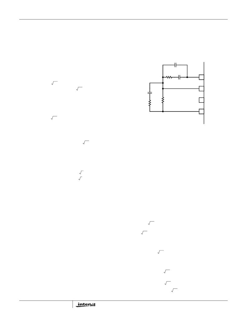
FIGURE 13. COMPENSATION CIRCUIT FOR ISL6557 BASED
CONVERTER WITHOUT LOAD-LINE
REGULATION.
I
COMP
C
C
R
C
R
FB
FB
IOUT
VDIFF
-
+
V
DROOP
C
2
C
1
R
1
R
1
R
FB
LC
–
C ESR
)
----------------------------------------
=
C
1
(
FB
)
--------------–
=
C
2
0.75V
2
π
(
)
f
0
f
HF
LCR
FB
V
PP
------------------------------------------------------------------
=
(EQ. 21)
R
C
R
V
2
π
0.75V
IN
2
π
f
HF
LC 1
2
f
f
LC
–
----------------------------------------------------------------
=
C
C
0.75V
2
π
f
LC
V
PP
R
FB
f
0
f
HF
LC
1
–
2
π
-------------------------------------------------------------------
=
ISL6557
相關(guān)PDF資料 |
PDF描述 |
|---|---|
| ISL6557 | PWM Controller with Wide Input Voltage Range 8-SOIC -20 to 85 |
| ISL6557CB | PWM Controller with Wide Input Voltage Range 8-PDIP -20 to 85 |
| ISL6558CRZA-T | Multi-Purpose Precision Multi-Phase PWM Controller With Optional Active Voltage Positioning |
| ISL6558IB | Multi-Purpose Precision Multi-Phase PWM Controller With Optional Active Voltage Positioning |
| ISL6558IB-T | Multi-Purpose Precision Multi-Phase PWM Controller With Optional Active Voltage Positioning |
相關(guān)代理商/技術(shù)參數(shù) |
參數(shù)描述 |
|---|---|
| ISL6557CB-T WAF | 制造商:Intersil Corporation 功能描述: |
| ISL6558CB | 功能描述:DC/DC 開關(guān)控制器 Precision MultiPhase RoHS:否 制造商:Texas Instruments 輸入電壓:6 V to 100 V 開關(guān)頻率: 輸出電壓:1.215 V to 80 V 輸出電流:3.5 A 輸出端數(shù)量:1 最大工作溫度:+ 125 C 安裝風(fēng)格: 封裝 / 箱體:CPAK |
| ISL6558CB-T | 功能描述:IC REG CTRLR BUCK PWM 16-SOIC RoHS:否 類別:集成電路 (IC) >> PMIC - 穩(wěn)壓器 - DC DC 切換控制器 系列:- 標(biāo)準(zhǔn)包裝:4,000 系列:- PWM 型:電壓模式 輸出數(shù):1 頻率 - 最大:1.5MHz 占空比:66.7% 電源電壓:4.75 V ~ 5.25 V 降壓:是 升壓:無 回掃:無 反相:無 倍增器:無 除法器:無 Cuk:無 隔離:無 工作溫度:-40°C ~ 85°C 封裝/外殼:40-VFQFN 裸露焊盤 包裝:帶卷 (TR) |
| ISL6558CBZ | 制造商:Intersil Corporation 功能描述:- Rail/Tube |
| ISL6558CBZA | 功能描述:DC/DC 開關(guān)控制器 W/ANNEAL 16LD N 2-4 PHS PWM BUCK CNTRLR RoHS:否 制造商:Texas Instruments 輸入電壓:6 V to 100 V 開關(guān)頻率: 輸出電壓:1.215 V to 80 V 輸出電流:3.5 A 輸出端數(shù)量:1 最大工作溫度:+ 125 C 安裝風(fēng)格: 封裝 / 箱體:CPAK |
發(fā)布緊急采購(gòu),3分鐘左右您將得到回復(fù)。