- 您現(xiàn)在的位置:買賣IC網(wǎng) > PDF目錄358013 > ITT8401FM RF/MICROWAVE WIDE BAND HIGH POWER AMPLIFIER PDF資料下載
參數(shù)資料
| 型號(hào): | ITT8401FM |
| 元件分類: | 放大器 |
| 英文描述: | RF/MICROWAVE WIDE BAND HIGH POWER AMPLIFIER |
| 文件頁(yè)數(shù): | 1/2頁(yè) |
| 文件大小: | 37K |
| 代理商: | ITT8401FM |

5W GaAs Power Amplifier (6.0 – 9.0 GHz)
ITT8401FM
ADVANCED
INFORMATION
Advanced Information - Specifications Subject to Change Without Notice
902100 B, February 1999
GaAsTEK
5310 Valley Park Drive
Roanoke, VA 24019 USA
www.gaastek.com
Tel: 1-540-563-3949
1-888-563-3949 (USA)
Fax: 1-540-563-8616
1
FEATURES
Broadband Performance
High Linear Power (P1dB): 35 dBm typical
High Power Added Efficiency: 30% typical at P1dB
High Linear Gain: 20 dB typical
50
Input/Output Impedance
Self-Aligned MSAG
MESFET Process
Unconditionally stable
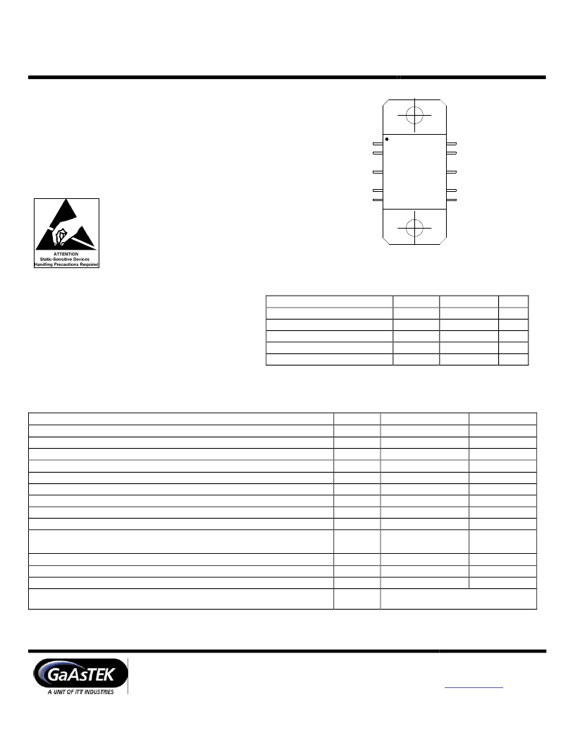
ITT
8401FM
Vgg
N/C
RFin
N/C
N/C
N/C
N/C
RFout
N/C
Vdd
DESCRIPTION
The ITT8401FM is a two stage MMIC power
amplifier fabricated on GaAsTEK’s mature GaAs
Self-Aligned MSAG
product is fully matched to 50 ohms on both the
input and the output and can be used as either a
driver or an output stage amplifier. Although it
can be used for several different applications, it is
ideally suited for VSAT and ISM applications.
MESFET Process. This
MAXIMUM RATINGS
(T
A
= 25 °C unless otherwise noted)
Rating
DC Drain Supply Voltage
DC Gate Supply Voltage
RF Input Power
Junction Temperature
Storage Temperature
Symbol
V
DD
V
GG
P
IN
T
J
T
STG
Value
12V
-4V
500
+175
-40 to +175
Unit
Vdc
Vdc
mW
°C
°C
ELECTRICAL CHARACTERISTICS
V
DD
=10.0 V, I
DQ
=900 mA, P
IN
=23 dBm, T
A
=25 °C
Characteristic
Frequency
Load Power
Power Gain
Power Gain Variation Over Frequency
Power Added Efficiency
(P
OUT
=34 dBm)
Drain Current
(P
OUT
=37 dBm)
Gate Bias Voltage
(No RF Input)
Gate Current
(P
OUT
=34 dBm)
Input VSWR
Harmonics
(
ο
=5.5 GHz, P
OUT
=34 dBm)
Symbol
P
OUT
G
P
Typical
6.0 to 9.0
37
12
±
0.5
35
1400
-1.9
Unit
GHz
dBm
dB
dB
%
mA
V
mA
I
DS
V
GG
I
GG
2:1
TBS
TBS
TBS
TBS
TBS
2
ο
3
ο
R
TH
dBc
dBc
°
C/W
dB
dBm
Thermal Resistance
(Junction of 2
nd
stage FET to T
FLANGE
, Note 1)
Noise Figure
Third-Order Intercept Point
(I
DQ
=525 mA)
Stability
(P
IN
= 10 to 27 dBm, V
DD
=3 to 10 V, Load VSWR = 3:1)
TOI
—
All non-harmonically related outputs
more than 70 dB below desired signal
Note 1: The second stage FET determines the overall thermal performance. Therefore, when performing thermal calculations, the dissipated power needs
only to be calculated for the amplifier’s 2
stage.
相關(guān)PDF資料 |
PDF描述 |
|---|---|
| ITT9013GU | 30 V, NPN, Si, SMALL SIGNAL TRANSISTOR, TO-92 |
| IVA-05208 | 0 MHz - 1500 MHz RF/MICROWAVE WIDE BAND LOW POWER AMPLIFIER |
| IVT-28P | 15 W, INVERTER TRANSFORMER |
| IVT-33P18 | 18 W, INVERTER TRANSFORMER |
| IVT-33P22 | 18 W, INVERTER TRANSFORMER |
相關(guān)代理商/技術(shù)參數(shù) |
參數(shù)描述 |
|---|---|
| ITT-946-5D | 制造商:ITT Interconnect Solutions 功能描述: |
| ITTAZ-DR | 制造商:FUJITSU Component Ltd 功能描述: 制造商:FUJITSU 功能描述: |
| ITU1131PJ75 | 制造商:Vishay Dale 功能描述:- Bulk |
| ITU1131PJ76 | 制造商:Vishay Dale 功能描述:- Bulk |
| ITU1329PJ17 | 制造商:Vishay Dale 功能描述:- Bulk |
發(fā)布緊急采購(gòu),3分鐘左右您將得到回復(fù)。