- 您現(xiàn)在的位置:買賣IC網(wǎng) > PDF目錄376008 > JA1A-TMP-AC12 PDF資料下載
參數(shù)資料
| 型號(hào): | JA1A-TMP-AC12 |
| 文件頁數(shù): | 2/4頁 |
| 文件大小: | 90K |
| 代理商: | JA1A-TMP-AC12 |

JA
111
COIL DATA
DC Type at 20
Nominal
voltage
12 V DC
24
°
C
68
°
F
Pick-up voltage
(max.)
9.6 V DC
19.2
AC Type at 20
Nominal
voltage
°
C
68
°
F
Pick-up voltage
(max.)
Drop-out* voltage
(min.)
1.2 (0.6*) V DC
2.4 (1.2*)
Coil resistance,
W (
±
10%)
120
480
Nominal operating
current, mA (
100
50
±
10%)
Nominal operating
power
1.2 W
1.2
Maximum allowable
voltage (at 50
13.2 V DC
26.4
°
C)
Drop-out* voltage
(min.)
Coil resistance,
W (
±
10%)
Nominal operating
current, mA (
50 Hz
117
58
12
±
10%)
60 Hz
108
54
11
Nominal operating
power
50 Hz
1.4 VA
1.4 VA
1.4 VA
Maximum allowable
voltage (at 50
°
C)
12 V AC
9.6 V AC
3.6 V AC
—
60 Hz
1.3 VA
1.3 VA
1.3 VA
13.2 V DC
24
115
19.2
92
7.2
34.5
—
—
26.4
126.5
* Drop-out voltage for 1 Form B type is 5% of nominal voltage.
NOTES
1. The range of coil current for AC relay is
Hz). For DC relay it is
±
10% at 20
°
C
68°F
.
2. The JA relay will operate in a range from 80% to
110% of the nominal coil voltage. It is however, recom-
mended that the relay be used in the range of 85% to
110% of the nominal coil voltage, with the temporary
voltage variation taken into consideration.
±
15% (60
3. When the operating voltage of AC relays drops be-
low 80% of the nominal coil voltage. The relay will gen-
erate a considerable amount of heat which is not
recommended for maximum efficiency.
4. The coil resistance of DC types is the measured val-
ue of the coil at a temperature of 20
coil temperature changes by
ue of the coil resistance should be increased or de-
creased by 0.4%.
°
C (
68
°
F
). If the
±
1
°
C. The measured val-
ADDITIONAL SERIES
1. Following up-graded contact rating types recognized by
UL are available. (For use in office appliances)
Suffix
Contact
arrangement
P (Ex. JA 1a - TM - DC12V -P)
1 Form C
1 Form A
1 Form B
25 A 250 V AC, 1 HP 125, 250 V AC
25 A 250 V AC, 1 HP 125, 250 V AC
25 A 250 V AC, 1 HP 125, 250 V AC
2. TV-Rated Series
Suffix
Contact
arrangement
UL
CSA
TV
TV
1 Form A
TV-5
TV-5
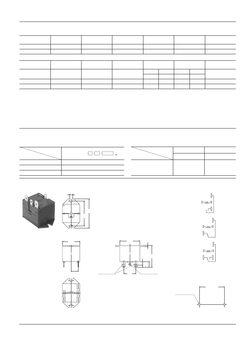
DIMENSIONS
TM
mm
inch
General tolerance:
±
0.3
±
.012
.177
1.969
1.713
COM
NO
NC
1.366
1.488
.366
.079
.846
FASTON 250
.500
1.185
R225
COM
.256
FASTON 187
Remarks
Above dimensions are for 1 Form C type.
For 1 Form A type, NC terminal is removed
For 1 Form B type, NO terminal is removed.
Schematic (Bottom view)
1 Form A
COM
N.O.
1 Form B
COM
N.C.
1 Form C
COM
N.C.
N.O.
Terminals—.187" quick connect terminals for coil
and .250" for contacts
Mounting hole location
Tolerance:
±
0.1
±
.004
±
1.713
±
.004
2-4.5
±
0.1 DIA.
2-.177
±
.004 DIA.
相關(guān)PDF資料 |
PDF描述 |
|---|---|
| JA1A-TMP-AC12-P | |
| JA1A-TMP-AC24 | |
| JA1A-TMP-AC24-P | |
| JA1A-TMP-DC12 | |
| JA1A-TMP-DC12-P | |
相關(guān)代理商/技術(shù)參數(shù) |
參數(shù)描述 |
|---|---|
| JA1A-TMP-AC12-P | 制造商:未知廠家 制造商全稱:未知廠家 功能描述: |
| JA1A-TMP-AC12V-P | 制造商:Panasonic Electric Works 功能描述: |
| JA1A-TMP-AC220V | 制造商:Panasonic Electric Works 功能描述: |
| JA1A-TMP-AC24 | 制造商:未知廠家 制造商全稱:未知廠家 功能描述: |
| JA1A-TMP-AC240V-P | 制造商:Panasonic Electric Works 功能描述: |
發(fā)布緊急采購,3分鐘左右您將得到回復(fù)。