- 您現(xiàn)在的位置:買賣IC網(wǎng) > PDF目錄365955 > KU80C188EC13 MICROPROCESSOR|16-BIT|CMOS|QFP|100PIN|PLASTIC PDF資料下載
參數(shù)資料
| 型號: | KU80C188EC13 |
| 英文描述: | MICROPROCESSOR|16-BIT|CMOS|QFP|100PIN|PLASTIC |
| 中文描述: | 微處理器| 16位|的CMOS | QFP封裝| 100引腳|塑料 |
| 文件頁數(shù): | 26/57頁 |
| 文件大小: | 585K |
| 代理商: | KU80C188EC13 |
第1頁第2頁第3頁第4頁第5頁第6頁第7頁第8頁第9頁第10頁第11頁第12頁第13頁第14頁第15頁第16頁第17頁第18頁第19頁第20頁第21頁第22頁第23頁第24頁第25頁當(dāng)前第26頁第27頁第28頁第29頁第30頁第31頁第32頁第33頁第34頁第35頁第36頁第37頁第38頁第39頁第40頁第41頁第42頁第43頁第44頁第45頁第46頁第47頁第48頁第49頁第50頁第51頁第52頁第53頁第54頁第55頁第56頁第57頁

80C186EC/188EC, 80L186EC/188EC
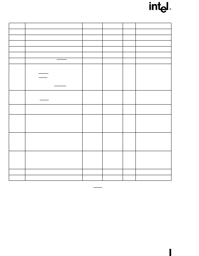
DC SPECIFICATIONS (80C186EC/80C188EC)
Symbol
Parameter
Min
Max
Units
Notes
V
CC
Supply Voltage
4.5
5.5
V
V
IL
Input Low Voltage
b
0.5
0.3 V
CC
V
CC
a
0.5
V
V
IH
Input High Voltage
0.7 V
CC
V
V
OL
Output Low Voltage
0.45
V
I
OL
e
3 mA (Min)
I
OH
e b
2 mA (Min)
V
OH
Output High Voltage
V
CC
b
0.5
V
V
HYR
Input Hysteresis on RESIN
0.5
V
I
LI
Input Leakage Current for Pins:
AD15:0 (AD7:0, A15:8), READY,
HOLD, RESIN,
CLKIN, TEST/BUSY, NMI, INT7:0,
T0IN, T1IN, P2.7–P2.0, P3.5–P3.0,
DRQ3:0, PEREQ, ERROR
g
15
m
A
0
s
V
IN
s
V
CC
I
LIU
Input Leakage for Pins with Pullups
Active During Reset:
A19:16, LOCK
b
0.275
b
5
mA
V
IN
e
0.7 V
CC
(Note 1)
I
LO
Output Leakage for Floated Output
Pins
g
15
m
A
0.45
s
V
OUT
s
V
CC
(Note 2)
I
CC
Supply Current Cold (in RESET)
80C186EC25
80C186EC20
80C186EC13
125
100
70
mA
mA
mA
(Notes 3, 7)
(Note 3)
(Note 3)
I
ID
Supply Current in Idle Mode
80C186EC25
80C186EC20
80C186EC13
92
76
50
mA
mA
mA
(Notes 4, 7)
(Note 4)
(Note 4)
I
PD
Supply Current in Powerdown Mode
80C186EC25
80C186EC20
80C186EC13
100
100
100
m
A
m
A
m
A
(Notes 5, 7)
(Note 5)
(Note 5)
C
IN
Input Pin Capacitance
0
15
pF
T
F
e
1 MHz
T
F
e
1 MHz (Note 6)
C
OUT
Output Pin Capacitance
0
15
pF
NOTES:
1. These pins have an internal pull-up device that is active while RESIN is low and ONCE Mode is not active. Sourcing more
current than specified (on any of these pins) may invoke a factory test mode.
2. Tested by outputs being floated by invoking ONCE Mode or by asserting HOLD.
3. Measured with the device in RESET and at worst case frequency, V
CC
, and temperature with
ALL
outputs loaded as
specified in AC Test Conditions, and all floating outputs driven to V
CC
or GND.
4. Measured with the device in HALT (IDLE Mode active) and at worst case frequency, V
CC
, and temperature with
ALL
outputs loaded as specified in AC Test Conditions, and all floating outputs driven to V
CC
or GND.
5. Measured with the device in HALT (Powerdown Mode active) and at worst case frequency, V
CC
, and temperature with
ALL
outputs loaded as specified in AC Test Conditions, and all floating outputs driven to V
CC
or GND.
6. Output Capacitance is the capacitive load of a floating output pin.
7. Operating conditions for 25 MHz is 0
§
C to
a
70
§
C, V
CC
e
5.0
g
10%.
26
相關(guān)PDF資料 |
PDF描述 |
|---|---|
| KU80C188EC-13 | 16-Bit Microprocessor |
| KU80C188EC20 | MICROPROCESSOR|16-BIT|CMOS|QFP|100PIN|PLASTIC |
| KU80C188EC-20 | 16-Bit Microprocessor |
| KU80C188EC-25 | 16-Bit Microprocessor |
| KU80L186EC13 | MICROPROCESSOR|16-BIT|CMOS|QFP|100PIN|PLASTIC |
相關(guān)代理商/技術(shù)參數(shù) |
參數(shù)描述 |
|---|---|
| KU80C188EC-13 | 制造商:未知廠家 制造商全稱:未知廠家 功能描述:16-Bit Microprocessor |
| KU80C188EC16 | 制造商:INTEL 制造商全稱:Intel Corporation 功能描述:16-BIT HIGH-INTEGRATION EMBEDDED PROCESSORS |
| KU80C188EC-16 | 制造商:未知廠家 制造商全稱:未知廠家 功能描述:16-Bit Microprocessor |
| KU80C188EC20 | 功能描述:IC MPU 16-BIT 5V 20MHZ 100-QFP RoHS:否 類別:集成電路 (IC) >> 嵌入式 - 微處理器 系列:- 標(biāo)準(zhǔn)包裝:2 系列:MPC8xx 處理器類型:32-位 MPC8xx PowerQUICC 特點(diǎn):- 速度:133MHz 電壓:3.3V 安裝類型:表面貼裝 封裝/外殼:357-BBGA 供應(yīng)商設(shè)備封裝:357-PBGA(25x25) 包裝:托盤 |
| KU80C188EC-20 | 制造商:未知廠家 制造商全稱:未知廠家 功能描述:16-Bit Microprocessor |
發(fā)布緊急采購,3分鐘左右您將得到回復(fù)。