- 您現(xiàn)在的位置:買賣IC網(wǎng) > PDF目錄383231 > L482 (意法半導(dǎo)體) HALL.EFFECT PICKUP IGNITION CONTROLLER PDF資料下載
參數(shù)資料
| 型號: | L482 |
| 廠商: | 意法半導(dǎo)體 |
| 英文描述: | HALL.EFFECT PICKUP IGNITION CONTROLLER |
| 中文描述: | HALL.EFFECT皮卡點火控制器 |
| 文件頁數(shù): | 3/11頁 |
| 文件大小: | 169K |
| 代理商: | L482 |
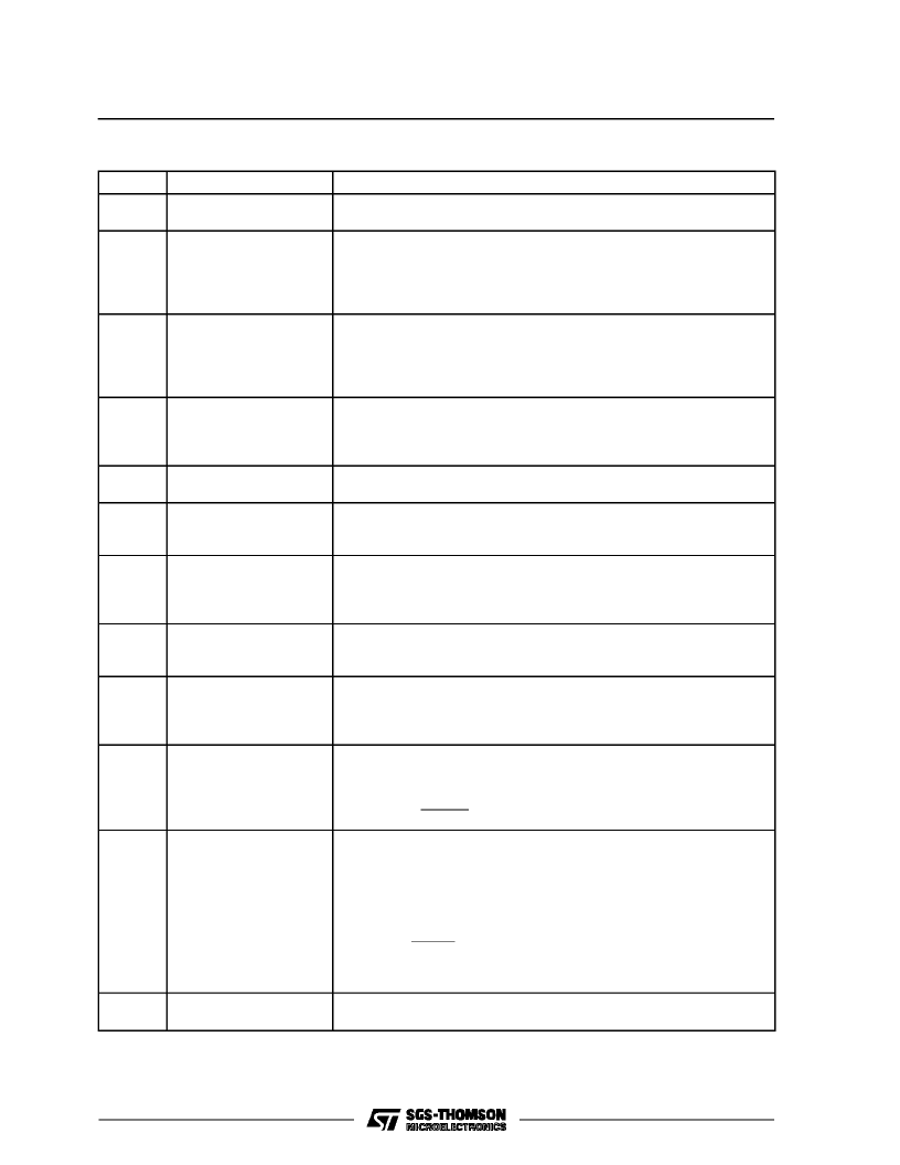
PINFUNCTIONS
(refer to fig. 3 for DIP16 package)
N
°
1
Name
Function
CONDUCTION TIME
SIGNAL
A low level on this output signal indicates when the external darlington is in
the ON condition i.e. when the current flows through the coil (ton in fig.1)
2
HALL-EFFECT INPUT
Hall-effect Pickup Input. A high level on this pin enables the current driving
into the coil. The effective coil charge will be a function of the dwell control
logic. A High to Low transition from the Hall-effect pickup is the signal for
ignition actuation. The input signal, supplied by the open collector output
stage of the Hall-effect sensor, has a duty cycle typically about 70%.
3
DWELL CONTROL
The average voltage on the capacitor C
2
connected between this pin and
ground depends on the motor speed and the voltage supply. The
comparison between V
C2
and V
C5
voltages determines the timing for the
dwell control. The recommended value is 100nF using a 100K
resistor at
pin 7. For the optimized operation of the device, C2 = C5.
4
DWELL CONTROL TIMER
The capacitor C5 connected between this pin and ground is charged when
the Hall-effect output is high and is discharged at the High to Low transition
of the Hall-effect signal. The recommended value is 100nF using a 100K
resistor at pin 7.
5
HALL SENSOR SUPPLY
This pin can be used to project the Hall-effect pickup against the voltage
transients, The resistor R
a
limits the current into the internal zener.
Open Collector Output Signal. This output is high when the external
darlington is in desaturation condition (current limitation), see t
d
pulse in fig.
1.
6
DESATURATION TIME
SIGNAL
7
REFERENCE VOLTAGE
A resistor R11 connected between this pin and ground sets the internal
current used to drive the external capacitors of the dwell control (C
2
and
C
5
) and permanent conduction protection (C
1
). The recommended value is
100K
.
A capacitor C1 connected between this pin and ground determines the
intervention delay of the permanent conduction protection, t
pc
of the figure 2.
With a 1
μ
F capacitor and 100K
resistor R
11
at pin 7 the typical delay is 1s.
A low pulse on this output detects the intervention of the permanent
conduction protection, as shown in figure 2. Typically the duration of the
time t
r
is more than 100
μ
s.
8
PERMANENT CONDUCT.
PROTECTION TIMER
9
PERMANENT CONDUCT.
RESET OUTPUT
(no available in
Micropackage) (*)
10
CURRENT SENSING
INPUT (*)
Connection for Coil Current Limitation. The current is measured on the
sense resistor R
S
and divided on R
1
/R
2
. The current limitation value is
given by :
I
SENS
=
V
SENS
R1
+
R2
R
S
R2
11
DUMP PROTECTION
(*)
The device is protected against the load dump. In load dump condition an
internal circuit,
based on a zener diode and a darlington transistor,
switches off the external darlington and short circuits the supply.
By means of the external divider R8/R9 the protection threshold can be
changed and is given as first approximation by:
V
Dth
=
8.5
R
8
+
R
9
R
9
+
5
10
4
R
8
(the resistor R9 value must be higher than 4K
).
12
POWER SUPPLY (*)
Supply Voltage Input. A 7V (typ) zener is present at the input. The external
resistor R
7
limits the current through the Zener for high supply voltages.
L482
3/11
相關(guān)PDF資料 |
PDF描述 |
|---|---|
| L482D1 | CAP 10UF 10V +80-20% Y5V SMD-1206 TR-7-PL SN100 |
| L484 | MAGNETIC PICKUP IGNITION CONTROLLER |
| L484D1 | MAGNETIC PICKUP IGNITION CONTROLLER |
| L4902A | DUAL 5V REGULATOR WITH RESET AND DISABLE |
| L4903 | DUAL 5V REGULATOR WITH RESET AND DISABLE FUNCTIONS |
相關(guān)代理商/技術(shù)參數(shù) |
參數(shù)描述 |
|---|---|
| L482/1 | 功能描述:馬達/運動/點火控制器和驅(qū)動器 Hall Effect Control RoHS:否 制造商:STMicroelectronics 產(chǎn)品:Stepper Motor Controllers / Drivers 類型:2 Phase Stepper Motor Driver 工作電源電壓:8 V to 45 V 電源電流:0.5 mA 工作溫度:- 25 C to + 125 C 安裝風格:SMD/SMT 封裝 / 箱體:HTSSOP-28 封裝:Tube |
| L482211G01 | 制造商:Eaton Corporation 功能描述:115 VOLT COIL FOR 230 VOLT DC CONTACTOR, TYPE M AND MD SIZE |
| L482D1 | 功能描述:馬達/運動/點火控制器和驅(qū)動器 Hall Effect Control RoHS:否 制造商:STMicroelectronics 產(chǎn)品:Stepper Motor Controllers / Drivers 類型:2 Phase Stepper Motor Driver 工作電源電壓:8 V to 45 V 電源電流:0.5 mA 工作溫度:- 25 C to + 125 C 安裝風格:SMD/SMT 封裝 / 箱體:HTSSOP-28 封裝:Tube |
| L482D1013TR | 功能描述:馬達/運動/點火控制器和驅(qū)動器 Hall Effect Control RoHS:否 制造商:STMicroelectronics 產(chǎn)品:Stepper Motor Controllers / Drivers 類型:2 Phase Stepper Motor Driver 工作電源電壓:8 V to 45 V 電源電流:0.5 mA 工作溫度:- 25 C to + 125 C 安裝風格:SMD/SMT 封裝 / 箱體:HTSSOP-28 封裝:Tube |
| L483 | 制造商:未知廠家 制造商全稱:未知廠家 功能描述:THYRISTOR MODULE|SCR DOUBLER|280V V(RRM)|22A I(T) |
發(fā)布緊急采購,3分鐘左右您將得到回復(fù)。