- 您現(xiàn)在的位置:買賣IC網(wǎng) > PDF目錄383231 > L484 (意法半導(dǎo)體) MAGNETIC PICKUP IGNITION CONTROLLER PDF資料下載
參數(shù)資料
| 型號(hào): | L484 |
| 廠商: | 意法半導(dǎo)體 |
| 英文描述: | MAGNETIC PICKUP IGNITION CONTROLLER |
| 中文描述: | 磁皮卡點(diǎn)火控制器 |
| 文件頁(yè)數(shù): | 3/11頁(yè) |
| 文件大?。?/td> | 156K |
| 代理商: | L484 |
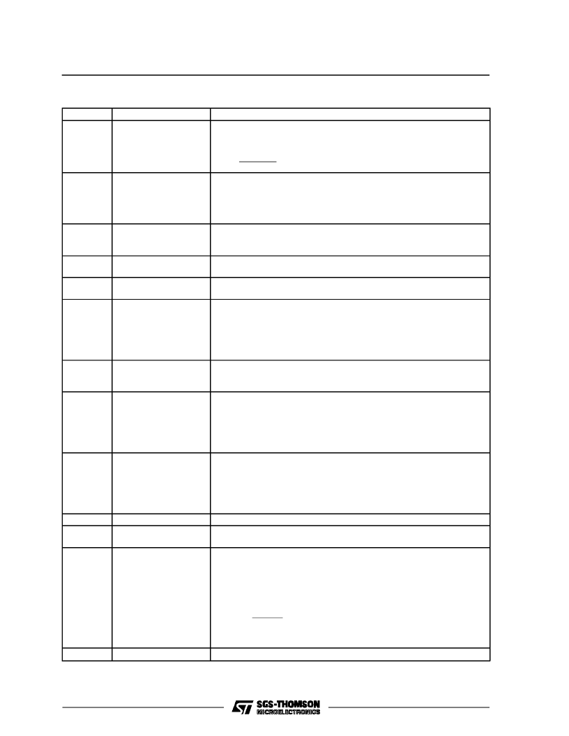
PINFUNCTIONS
(refer to fig. 2)
N
°
1
Name
Function
CURRENT SENSING
INPUT
Connection for Coil Current Limitation. The current is measured on the
sense resistor R
SENS
and divided on R1/R2. The current limitation value is
given by :
R1
+
R2
R
SENS
R2
Magnetic Pickup Signal Input. This pin sets the dwell time,
negative pickup voltage value starting from which the device can drive the
current into the coil. The real dwell time will be a function of the dwell
control logic. Increasing the resistor R11 the maximum conduction time
increases. The max input current foreseen is 2mA.
A capacitor C1 connected between this pin and ground sets the delay of the
permanent conduction protection in the coil current. Using a 50nF capacitor
the typical desaturation time delay for the protection is 75ms.
A low level on this input (max 0.7V) disables the protection, irrespective of
the state of pin 3. If the protection is used this pin must be left open.
Open collector output signal which is at a low level when the final darlington
is in ON status. The current is internally limited at 10mA.
At high motor rotation speeds,
i.e. when the peak value of the magnetic
pick-up signal exceedes 6V using R12 = 100K
, this pin may be used to
vary the dwell ratio. Adding a resistor in series R
a
between this pin and pin
11 the desaturation time is reduced. It is therefore possible to use this pin to
adapt the L484 to various pickup types. The maximum value of the resistor
R
a
is 200K
.
A capacitor C2 connected between this pin and ground sets the timing for
the dwell control. The recommended value is 100nF. The resistors R
b
/R
c
provide an hysteresis to confirm ON state and avoid spurious sparks.
Zero cross detector input of the magnetic pickup signal for the ignition
actuation. At high motor rotation speeds, the external resistor R12 may be
used to vary the
desaturation time ratio,
signal waveforms of time magnetic pick-up. Reducing the resistor value the
dwell time increases. Typically the range of values for resistor R12 is from
50K
to 150K
..
A low level on this pin forces the external darlington into conduction
particularly useful in anti knock system. This function is particularly useful in
antiknock system because provides a spark time delay. Anyway the current
limitation,
the permanent conduction protection and the dump protection
are operating even when pin 9 is at a low level. If this function is not used it
must be left open.
This pin must be connected to ground.
Supply Voltage Input. A 7V (typ) zener is present at the input. The external
resistor R9 limits the current through the zener for higher supply voltages.
The device is protected against the load dump. In load dump condition an
internal circuit,
based on a zener diode and a darlington transistor,
switches off the external darlington and short circuits the supply.
By means of the external divider R8/R9 the protection threshold can be
changed and is given as first approximation by:
I
SENS
=
2
PICKUP INPUT
i.e. the max
3
PERMANENT
CONDUCT.
PROTECTION TIMER
PERMANENT CONDUCT.
PROTECTIONINHIBIT
RPM OUTPUT
4
5
6
DWELL TIME ADJUST
7
DWELL CONTROL
TIMER
8
ZERO CROSSING
INPUT
to adapt the L484 to various
9
POWER-ON INPUT
10
11
SIGNAL GROUND
POWER SUPPLY
12
DUMP PROTECTION
V
Dth
=
8.5
R8
+
R9
R9
+
5
10
4
R8
(the resistor R9 value must be higher than 4K
).
This pin must be connected to ground.
13
POWER GROUND
* thisfunction is particularly useful in antiknock systeme because provides a sparktime delay. anyway the current limitation,the pemanent con
duction protection and thedump protection are operating even when pin 9 is at a low level.
L484
3/11
相關(guān)PDF資料 |
PDF描述 |
|---|---|
| L484D1 | MAGNETIC PICKUP IGNITION CONTROLLER |
| L4902A | DUAL 5V REGULATOR WITH RESET AND DISABLE |
| L4903 | DUAL 5V REGULATOR WITH RESET AND DISABLE FUNCTIONS |
| L4904A | DUAL 5V REGULATOR WITH RESET |
| L4909 | EXTERNALLY ADJUSTABLE MULTIFUNCTION REGULATOR |
相關(guān)代理商/技術(shù)參數(shù) |
參數(shù)描述 |
|---|---|
| L484D1 | 功能描述:馬達(dá)/運(yùn)動(dòng)/點(diǎn)火控制器和驅(qū)動(dòng)器 Magnetic Control RoHS:否 制造商:STMicroelectronics 產(chǎn)品:Stepper Motor Controllers / Drivers 類型:2 Phase Stepper Motor Driver 工作電源電壓:8 V to 45 V 電源電流:0.5 mA 工作溫度:- 25 C to + 125 C 安裝風(fēng)格:SMD/SMT 封裝 / 箱體:HTSSOP-28 封裝:Tube |
| L484D1013TR | 功能描述:馬達(dá)/運(yùn)動(dòng)/點(diǎn)火控制器和驅(qū)動(dòng)器 Magnetic Control RoHS:否 制造商:STMicroelectronics 產(chǎn)品:Stepper Motor Controllers / Drivers 類型:2 Phase Stepper Motor Driver 工作電源電壓:8 V to 45 V 電源電流:0.5 mA 工作溫度:- 25 C to + 125 C 安裝風(fēng)格:SMD/SMT 封裝 / 箱體:HTSSOP-28 封裝:Tube |
| L485 | 制造商:LAUREL ELECTRONICS 功能描述:Modbus RS485, dual RJ11, communications plug-in board Laureate meters and counters. ;RoHS Compliant: Yes |
| L486 | 制造商:IXYS 制造商全稱:IXYS Corporation 功能描述:IGBT Modules Sixpack, H Bridge |
| L4863 | 制造商:UTC-IC 制造商全稱:UTC-IC 功能描述:DUAL 2.2W AUDIO AMPLIFIER PLUS STEREO HEADPHONE FUNCTION |
發(fā)布緊急采購(gòu),3分鐘左右您將得到回復(fù)。