- 您現(xiàn)在的位置:買(mǎi)賣(mài)IC網(wǎng) > PDF目錄383236 > L6380 (意法半導(dǎo)體) High Voltage High-Side Driver(高壓高邊驅(qū)動(dòng)器) PDF資料下載
參數(shù)資料
| 型號(hào): | L6380 |
| 廠商: | 意法半導(dǎo)體 |
| 英文描述: | High Voltage High-Side Driver(高壓高邊驅(qū)動(dòng)器) |
| 中文描述: | 高電壓高邊驅(qū)動(dòng)器(高壓高邊驅(qū)動(dòng)器) |
| 文件頁(yè)數(shù): | 2/9頁(yè) |
| 文件大?。?/td> | 75K |
| 代理商: | L6380 |
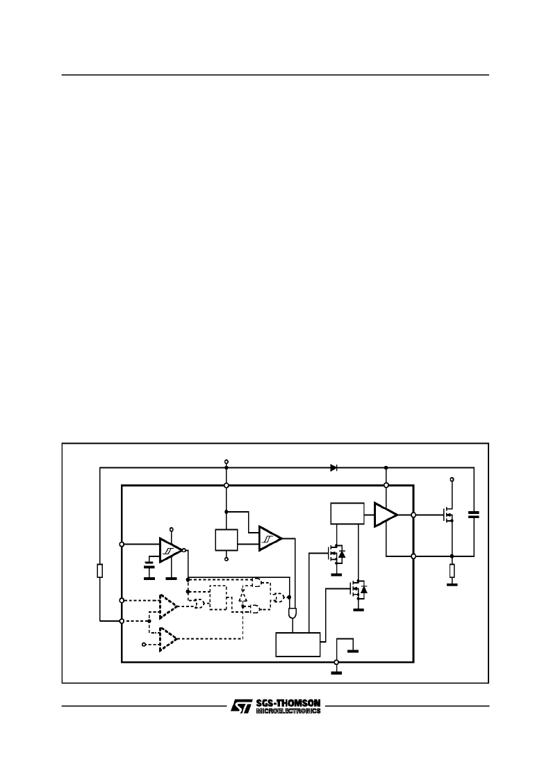
To drive the external power device the signal
coming from input logic is fed into a pulse gener-
ator that in turns drives the level shifting sructure
(that include two High Voltage DMOS) designed
to ensure low power dissipation and high noise
immunity. The output buffer (in Totem Pole ar-
rangement) is able to sink from or source to the
gate of the external device the current needed to
switch it ON or OFF.
The falling edge of the signal coming from the in-
put logic will turn ON while the rising edge will
turn OFF the driven power device. This operation
will ensure low current sinking from the HV rail
during commutations.
Current / VoltageMode Operation
To select the Voltage Mode Operation the user
have to set on the RI pin a voltage higher than
the internal reference (7V). In this way the IC will
function as an inverting buffer driven by the LI in-
put pin (seeVoltage Mode Timing Diagram).
If the voltage on RI input pin is lower than 7V the
Current Mode Operation will be enabled. In this
configuration the RI input will set the reference
voltage to the non inverting input of the Current
Mode Comparator (see block diagram), whose in-
verting input, the CI input pin, in allowable to
close a current control loop with a voltage drop
coming from a sense resistor. To summarise (see
CurrentMode Timing Diagrams):
The output of the Current Mode Comparator will
mask the LI input whenever the CI voltage is
higher than the RI input (and the RI voltageis be-
low 7V).
Under Voltage Lockout
The output buffer if switched off wheneverVs de-
creasebelow Vth OFF.
The IC will remail in this shut down status until Vs
has risen above VthON, the hysteresis will pro-
vide a good noise immunity.
Applications
The L6380/L6381 can be used in motor control
applications (AC, DC and switched reluctance),
electronicballasts, heating and welding, switching
power supplies and UPS.
+
-
-
+
7 V
+
-
Current
Mode
Voltage
Mode
LEVEL
SHIFTER
B.
G.
REG.
LI
CI
VS
7V
10V
Under
Voltage
Comparator
ON
OFF
OUT
BOOT
H.V.
VS
VS
HVG
GND
D94IN078
RI
PULSE
GENERATOR
1.4V
S
R
Q
20K
LOAD
L6381 BLOCK DIAGRAM
L6380 - L6381
2/9
相關(guān)PDF資料 |
PDF描述 |
|---|---|
| L6381 | High Voltage High-Side Driver(高壓高邊驅(qū)動(dòng)器) |
| L6382D_07 | Power management unit for microcontrolled ballast |
| L6382D5 | POWER MANAGEMENT UNIT FOR MICROCONTROLLED BALLAST |
| L6382D5TR | POWER MANAGEMENT UNIT FOR MICROCONTROLLED BALLAST |
| L6382D | Power management unit for microcontrolled ballast |
相關(guān)代理商/技術(shù)參數(shù) |
參數(shù)描述 |
|---|---|
| L6381 | 制造商:未知廠家 制造商全稱(chēng):未知廠家 功能描述: |
| L63815-000 | 制造商:TE Connectivity 功能描述:362A114-4-0-CS8436 - Bulk |
| L6381D | 制造商:STMicroelectronics 功能描述:Single MOSFET DRIVER, 8 Pin, Plastic, SOP |
| L6382D | 功能描述:PMIC 解決方案 PFC and Ballast Controller RoHS:否 制造商:Texas Instruments 安裝風(fēng)格:SMD/SMT 封裝 / 箱體:QFN-24 封裝:Reel |
| L6382D_07 | 制造商:STMICROELECTRONICS 制造商全稱(chēng):STMicroelectronics 功能描述:Power management unit for microcontrolled ballast |
發(fā)布緊急采購(gòu),3分鐘左右您將得到回復(fù)。