- 您現(xiàn)在的位置:買賣IC網(wǎng) > PDF目錄30715 > LA2110 SPECIALTY CONSUMER CIRCUIT, PZIP16 PDF資料下載
參數(shù)資料
| 型號(hào): | LA2110 |
| 元件分類: | 消費(fèi)家電 |
| 英文描述: | SPECIALTY CONSUMER CIRCUIT, PZIP16 |
| 封裝: | SIP-16 |
| 文件頁數(shù): | 5/7頁 |
| 文件大?。?/td> | 94K |
| 代理商: | LA2110 |

LA2110
No.855-5/7
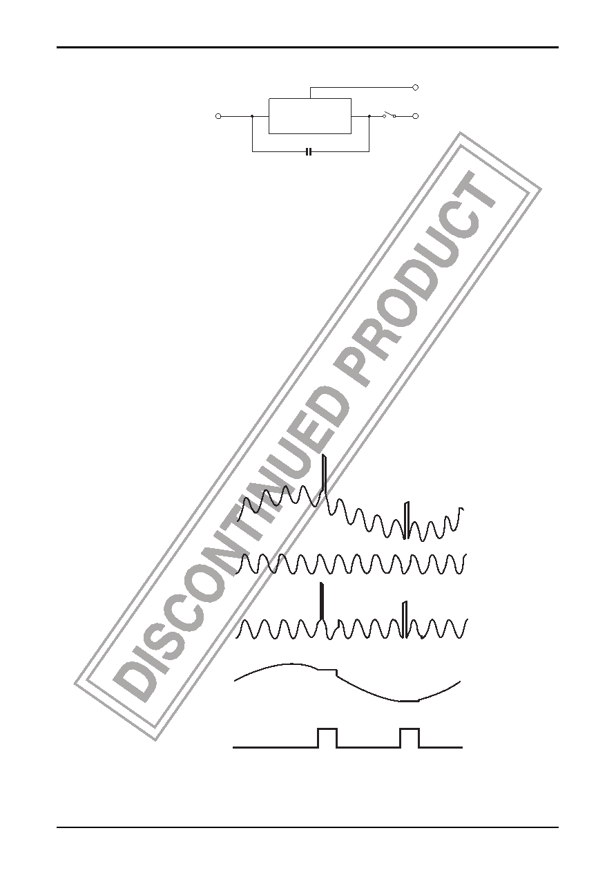
Theory of LA2110 Noise Canceller
In order to simplify the operation theory, the composite signal component is given only as a low frequency signal and a
pilot cancel signal has the same phase, same amplitude as the pilot signal in the composite signal.
Since the output voltage is the differential voltage of the plus and minus input of the subtraction circuit, it is equal to the
voltage between the memory capacitor terminals. When the gate is closed, the composite signal is applied to the plus
input terminal of the subtraction circuit, and the pilot cancel signal is applied to the minus input terminal. Thus the pilot
signal is cancelled from the output and only the low frequency signal appears. In the same way, the voltage between the
memory capacitor terminals is the differential voltage of the composite signal and the pilot cancel signal, so only the
low frequency signal appears.
When pulse noise is generated and the gate opens, the plus input and minus input signal waveforms of the subtraction
circuit become equal. This is because the input impedance of the subtraction circuit is extremely high, so the memory
capacitor is considered AC-shorted. Thus, when pulse noise is generated in the composite signal, the same pulse noise
appears in minus as well as plus input of the subtraction circuit. As a result, pulse noise does not appear in the output.
The voltage in the output has a DC level difference of plus and minus input, and that is the voltage held by the memory
capacitor. This voltage is that between the memory capacitor terminals just before the gate opens, so it is the low
frequency signal voltage just before the gate opens. Because the subtraction circuit input impedance is high, no
charge/discharge current flows in the memory capacitor while the gate is open, so the memory capacitor can hold the
voltage between its terminals.
The voltage waveforms are illustrated below.
Note : The pilot cancel signal is given as sinusoidal in this explanation, but in the actual application circuit, pilot
cancel is performed by a triangular wave.
Subtraction
circuit
Memory capacitor
Composite signal output
Pilot canceller
signal input
Output
+-
Closed
Open
Composite signal
Pilot cancel signal
Subtraction circuit
minus input
Output, and voltage
between memory
capacitor terminals
Gate control pulse
Open
相關(guān)PDF資料 |
PDF描述 |
|---|---|
| LA2113 | SPECIALTY CONSUMER CIRCUIT, PDIP16 |
| LA2120M | SPECIALTY CONSUMER CIRCUIT, PDSO16 |
| LA2200 | SPECIALTY CONSUMER CIRCUIT, PDIP16 |
| LA2205 | SPECIALTY CONSUMER CIRCUIT, PZIP16 |
| LA2220 | SPECIALTY CONSUMER CIRCUIT, PZIP22 |
相關(guān)代理商/技術(shù)參數(shù) |
參數(shù)描述 |
|---|---|
| LA2113 | 制造商:SANYO 制造商全稱:Sanyo Semicon Device 功能描述:FM Noise Canceler |
| LA212 | 制造商:未知廠家 制造商全稱:未知廠家 功能描述:Photocoupler |
| LA2120M | 制造商:SANYO 制造商全稱:Sanyo Semicon Device 功能描述:LA2120M |
| LA212B-G | 制造商:LIGITEK 制造商全稱:LIGITEK electronics co., ltd. 功能描述:LED ARRAY |
| LA212B-G-PF | 制造商:LIGITEK 制造商全稱:LIGITEK electronics co., ltd. 功能描述:LED ARRAY |
發(fā)布緊急采購,3分鐘左右您將得到回復(fù)。