- 您現(xiàn)在的位置:買賣IC網(wǎng) > PDF目錄30716 > LA2650 SPECIALTY CONSUMER CIRCUIT, PDIP20 PDF資料下載
參數(shù)資料
| 型號: | LA2650 |
| 元件分類: | 消費家電 |
| 英文描述: | SPECIALTY CONSUMER CIRCUIT, PDIP20 |
| 封裝: | DIP-20 |
| 文件頁數(shù): | 2/13頁 |
| 文件大小: | 318K |
| 代理商: | LA2650 |

Recommended Data Transfer Procedure
The boost gain select and the left and right channel boost add on/off settings should only be set at power on. During
normal operation, control the device by setting the add level select and boost on/off settings. Using the add level select
and boost on/off settings for control is superior from the standpoint of minimizing switching noise (spikes).
Limiter (ALC) Operation
The level limiter operates when the boost gain amplifier output level reaches about 2 V rms, and suppress further level
increases above that point.
The non-clipping limiter operates to prevent boost gain amplifier output clipping at power-supply voltages (about 8.5 V
and lower) at which the output cannot be amplified to the operating level of the level limiter.
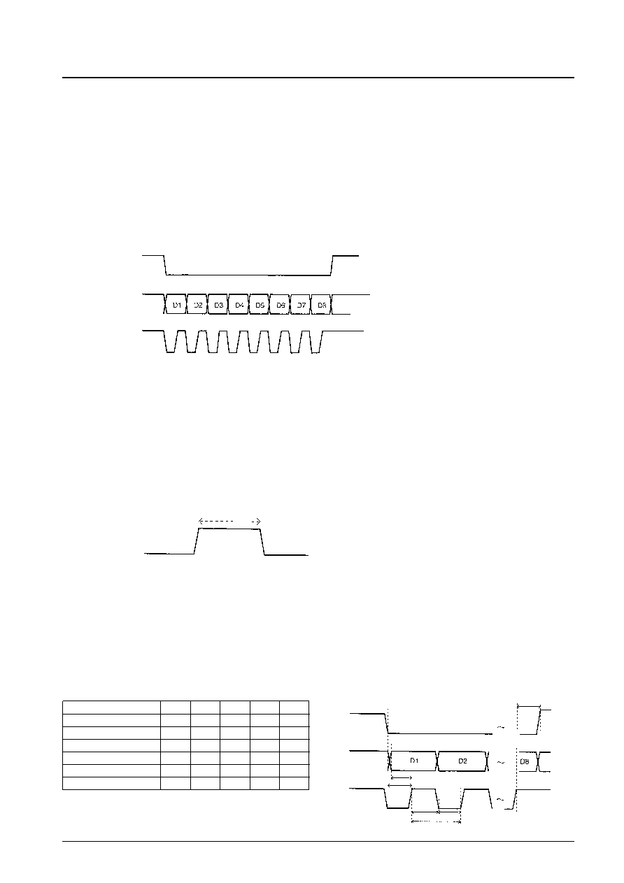
Notes on Control Data
— Data is read in on the rising edge of the clock signal.
— Data consists of 8 bits, D1 through D8.
— The input data is latched on the rising edge of the enable signal.
— When the LA2650 is not being controlled, the clock and the enable signal must be held high.
— Intervals between commands
The timing of the intervals on the enable signal must meet the conditions shown in the figure below.
Initial Settings at Power on
— All data is reset to low when power is first applied.
— Applications should send their initial data settings once the IC is fully operational after power is applied, i.e. about
0.5 second after power is applied.
Data Timing
No. 5652-10/13
LA2650
Timing characteristics
min
typ
max
unit
Enable clock delay time
tec
5
s
Data clock delay time
tdc
5
s
Clock high-level hold time
tch
5
s
Clock low-level hold time
tcl
5
s
Clock enable delay time
tce
5
s
Clock cycle time
tck
10
s
At least 10 s
Enable
tce
tch
tec
tdc
tck
tcl
Data
Clock
相關(guān)PDF資料 |
PDF描述 |
|---|---|
| LA2655V | SPECIALTY CONSUMER CIRCUIT, PDSO20 |
| LA2657M | SPECIALTY CONSUMER CIRCUIT, PQFP64 |
| LA2775 | SPECIALTY CONSUMER CIRCUIT, PDIP14 |
| LA2730 | B Type, DOLBY NOISE REDUCTION IC, PDIP16 |
| LA2787 | SPECIALTY CONSUMER CIRCUIT, PDIP48 |
相關(guān)代理商/技術(shù)參數(shù) |
參數(shù)描述 |
|---|---|
| LA2655V | 制造商:SANYO 制造商全稱:Sanyo Semicon Device 功能描述:Clear Sound Control IC Loading Plus Sound Algorithm |
| LA265B-H-1-PF | 制造商:LIGITEK 制造商全稱:LIGITEK electronics co., ltd. 功能描述:LED ARRAY |
| LA265W-G-PF | 制造商:LIGITEK 制造商全稱:LIGITEK electronics co., ltd. 功能描述:LED ARRAY |
| LA266B-HRDBK-2-PF | 制造商:LIGITEK 制造商全稱:LIGITEK electronics co., ltd. 功能描述:LED ARRAY |
| LA266B-HRDBK-PF | 制造商:LIGITEK 制造商全稱:LIGITEK electronics co., ltd. 功能描述:LED ARRAY |
發(fā)布緊急采購,3分鐘左右您將得到回復。