- 您現(xiàn)在的位置:買賣IC網(wǎng) > PDF目錄358727 > LA2806M (Sanyo Electric Co.,Ltd.) Signal Processor and Power Amplifier IC for Telephone Answering Machines PDF資料下載
參數(shù)資料
| 型號(hào): | LA2806M |
| 廠商: | Sanyo Electric Co.,Ltd. |
| 英文描述: | Signal Processor and Power Amplifier IC for Telephone Answering Machines |
| 中文描述: | 信號(hào)處理器和功放的IC電話答錄機(jī) |
| 文件頁(yè)數(shù): | 5/11頁(yè) |
| 文件大小: | 177K |
| 代理商: | LA2806M |
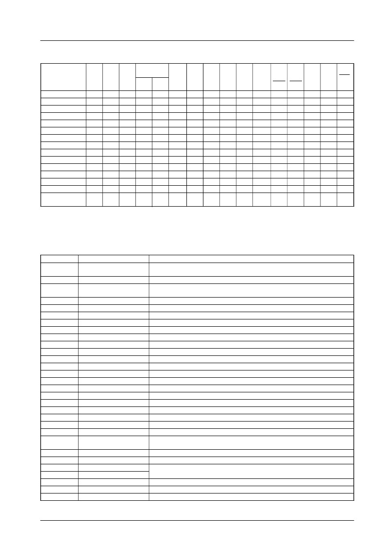
Mode Selection
Mode
REC
ON/
OFF
LINE
ON/
OFF
PWR
ON/
OFF
INPUT
MUTE
SW1/
SW11
ICM
REC
×
1
1
1
1
0
0
0
0
0
0
0
0
0
SW2
ICM
PLAY
SW3
LINE
SW4
MIC
SW5
MUTE
SW6
PRE/
OGM
SW7
MONI
/OGM
SW8
LINE
SW9
PWR
SW10
PRE/
EQ
D1
D0
MUTE
ICM REC
2WAY REC
DICT REC
2WAY BEEP
ICM OUT
ICM PLAY
OGM REC
OGM CHANGE
OGM OUT
OGM PLAY
ROOM MONI
ROOM OUT
VOICE SELE
Conversation
recording
×
×
×
×
×
HIGH
LOW
LOW
LOW
LOW
LOW
LOW
LOW
LOW
LOW
LOW
LOW
LOW
LOW
×
0
0
0
0
1
1
0
0
0
0
0
0
0
×
1
1
0
1
0
0
0
1
1
1
0
1
1
×
0
0
1
0
0
0
1
0
0
0
1
0
0
0
1
1
1
1
1
1
1
1
1
1
1
1
1
×
1
1
1
0
1
1
1
1
0
0
1
1
1
×
1
1
1
1
1
1
1
1
1
1
1
1
0
×
0
0
0
1
1
0
0
0
1
0
1
0
1
×
1
0
0
1
1
1
0
1
1
1
0
1
1
×
0
0
0
0
1
1
0
0
0
0
0
0
0
HIGH LOW HIGH HIGH HIGH
HIGH LOW
LOW HIGH HIGH
HIGH LOW
LOW HIGH LOW
HIGH HIGH HIGH LOW HIGH
LOW HIGH HIGH LOW
LOW
LOW HIGH LOW
LOW
LOW
LOW HIGH LOW
LOW
LOW HIGH HIGH HIGH
LOW HIGH HIGH LOW HIGH
LOW
LOW HIGH LOW HIGH
LOW HIGH LOW HIGH LOW
LOW
LOW HIGH HIGH HIGH
LOW HIGH HIGH HIGH HIGH
LOW
LOW
HIGH HIGH HIGH HIGH HIGH
LOW
1
0
1
0
1
1
0
1
1
0
Notes
2WAY BEEP : LINE OUT –6 dB
1 = ON and 0 = OFF (SW1 to SW5, SW8, SW9 and SW11)
Pin Functions
Pin No.
Pin name
Functions
1
BIAS/GAIN
Bias. Recording amplifier gain and recording bias current controled by external
resistor.
Incoming head input/output
Playback amplifier feedback. Receives negative feedback input from PRE OUT
(pin 8).
Preamplifier ground
Line input
Microphone input
Preamplifier feedback. Receives negative feedback input from PRE OUT (pin 8).
Preamplifier/playback amplifier output
Automatic level control time constant adjust input
Preamplifier/playback amplifier output signal input
Outgoing message/beep input
Filter amplifier negative feedback input
Filter amplifier output
Internal reference voltage output (Approx. 2.2 V)
Preamplifier supply
Power amplifier ground
Power amplifier output
Power amplifier supply
Power amplifier reference voltage output (Approx. 4/9 x P.V
CC
)
Power amplifier input
Power amplifier monitor output
Line amplifier output
Voice-operated switch (VOX) threshold adjust input. VOX sensitivity can be adjusted
by connecting this signal to the V
REF
pin (pin 14) via a resistor.
Voice-operated switch (VOX) detection and mute control
Voice-operated switch (VOX) open-collector output
Incoming message, line, microphone and outgoing message/beep analog switch
control inputs.
Power amplifier ON/OFF analog switch control input
Line amplifier ON/OFF analog switch control input
Recording amplifier ON/OFF analog switch control input
2
ICM
3
PB NF
4
5
6
7
8
9
GND
LINE
MIC
PRE NF
PRE OUT
ALC. CT
SIG IN
OGM/BEEP
FIL NF
FIL OUT
V. REF
V
CC
P.GND
PWR OUT
P.V
CC
D.C
PWR IN
PWR MONI
LINE OUT
10
11
12
13
14
15
16
17
18
19
20
21
22
23
TH
24
25
26
27
28
29
30
VOX. C/MUTE
VOX
D0
D1
PWR ON/OFF
LINE ON/OFF
REC ON/OFF
LA2806M
No. 3852 - 5/11
相關(guān)PDF資料 |
PDF描述 |
|---|---|
| LA2900 | Two-Channel High-Output Line Amplifier for Car Audio Systems |
| LA2900M | Two-Channel High-Output Line Amplifier for Car Audio Systems |
| LA2901 | Four-Channel High-Output Line Amplifier for Car Audio Systems |
| LA2901V | Four-Channel High-Output Line Amplifier for Car Audio Systems |
| LA305-S | Current Transducer LA 305-S |
相關(guān)代理商/技術(shù)參數(shù) |
參數(shù)描述 |
|---|---|
| LA282B-1-DGM-1-PF | 制造商:LIGITEK 制造商全稱:LIGITEK electronics co., ltd. 功能描述:LED ARRAY |
| LA282B-1-DGM-PF | 制造商:LIGITEK 制造商全稱:LIGITEK electronics co., ltd. 功能描述:LA282B-1-DGM-PF |
| LA282B-1-VY-1-PF | 制造商:LIGITEK 制造商全稱:LIGITEK electronics co., ltd. 功能描述:LED ARRAY |
| LA282B-1-VY-PF | 制造商:LIGITEK 制造商全稱:LIGITEK electronics co., ltd. 功能描述:LED ARRAY |
| LA284B-G-PF | 制造商:LIGITEK 制造商全稱:LIGITEK electronics co., ltd. 功能描述:LED ARRAY |
發(fā)布緊急采購(gòu),3分鐘左右您將得到回復(fù)。