- 您現(xiàn)在的位置:買賣IC網(wǎng) > PDF目錄367503 > LA4460N PDF資料下載
參數(shù)資料
| 型號: | LA4460N |
| 元件分類: | 音頻放大器 |
| 文件頁數(shù): | 5/12頁 |
| 文件大?。?/td> | 477K |
| 代理商: | LA4460N |

LA4460N, 4461N
No.2660–5/12
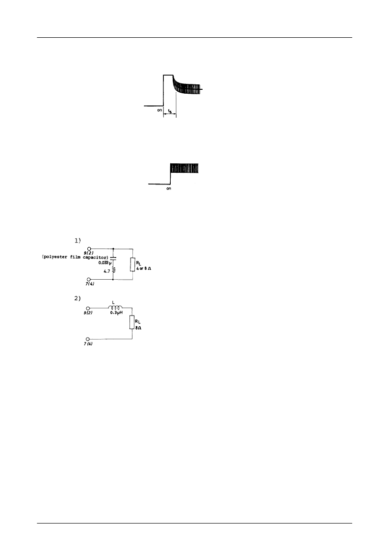
c) Starting time adjustment resistor R
X
The purpose of the R
X
is to adjust the starting time ts, and a resistor of 1.5k
is used. In this case, a rising DC locus
as shown below will be obtained at the output terminals.
The circuit has been set to provide signals about 0.4
μ
s. after the power is turned on. Though the ts will increase with
decreasing R
X
, the total output across the load will be decreased, since the signal flowing to the non-inverted side will
flow into the ground through the R
X
. Contrarily, increasing the R
X
to R
X
=
∞
as shown in the Sample Application
Circuit 2, the ts reduces to zero s., and the rising locus as shown below will be obtained.
d) Oscillation compensation CR across the load
To prevent parasitic oscillation, it is recommended to connect 0.033
μ
F plus 4.7
between each channel output termi-
nal and GND. (As a rule the capacitor should be a polyester film capacitor.) This measure against the oscillation may
be replaced with the methods as shown below, depending upon the stability of PC boards used.
Note :
· Check for oscillation at low temperatures.
· Check for oscillation on stereo PC boards.
· Do not use shielded wires for output cords.
Note :
· Check for oscillation at low temperatures.
· Use 8
load resistor.
· Do not use shielded wires for output cords.
· L should be higher than 0.3
μ
H.
(Removal of oscillation compensation CR)
Coil used
Air core
Wire size : UEW 1.5
Above examples can be applied to the Sample Application Circuits 1, 2.
Inner diameter : 8
Winding method : Solenoid (0.3
μ
H)
Number of turns : 6 turns
Features of IC System and Roles of the Remaining Pin Terminals
· Since a zero-bias design is introduced into the input circuit to keep the input potential at about zero by employing PNP
in the input circuit, an input coupling capacitor can be removed for direct connection. However, when noises caused by
a DC current flowing to a volume control circuit or the input circuit causes problems, connect a capacitor in series with
the input circuit.
· To prevent damage or deterioration of the IC due to the load short-circuited, a load short-circuit current limiting type
protection circuit has been provided.
However, when making the load short-circuit test, always mount the IC on the specified heat sink.
· A circuit which prevents pop noise caused by the power on-off operation is also provided, thereby reducing the offset
voltage and protecting speaker systems against damage.
Continued on next page.
相關(guān)PDF資料 |
PDF描述 |
|---|---|
| LA4461N | |
| LA4530M | |
| LA4530S | |
| LA4533 | |
| LA4570 | Analog IC |
相關(guān)代理商/技術(shù)參數(shù) |
參數(shù)描述 |
|---|---|
| LA4461 | 制造商: 功能描述:4461 |
| LA4461N | 制造商: 功能描述:Audio Amplifier Circuit, Dual, 10 Pin, Plastic, SIP |
| LA4465 | 制造商:SANYO 制造商全稱:Sanyo Semicon Device 功能描述:BTL-OCL 12W AF Power Amp For Car Stereo Use |
| LA4466 | 制造商:SANYO 制造商全稱:Sanyo Semicon Device 功能描述:BTL-OCL 12W AF Power Amp For Car Stereo Use |
| LA4470 | 制造商:SANYO 制造商全稱:Sanyo Semicon Device 功能描述:BTL-OCL 20W Power Amp For Car Stereo Use |
發(fā)布緊急采購,3分鐘左右您將得到回復(fù)。