- 您現(xiàn)在的位置:買賣IC網(wǎng) > PDF目錄30719 > LA4919N 10 W, 2 CHANNEL, AUDIO AMPLIFIER, PDFM28 PDF資料下載
參數(shù)資料
| 型號: | LA4919N |
| 元件分類: | 音頻/視頻放大 |
| 英文描述: | 10 W, 2 CHANNEL, AUDIO AMPLIFIER, PDFM28 |
| 封裝: | 0.500 INCH, DIP-28 |
| 文件頁數(shù): | 5/6頁 |
| 文件大小: | 78K |
| 代理商: | LA4919N |

LA4919N
No.A0323-5/6
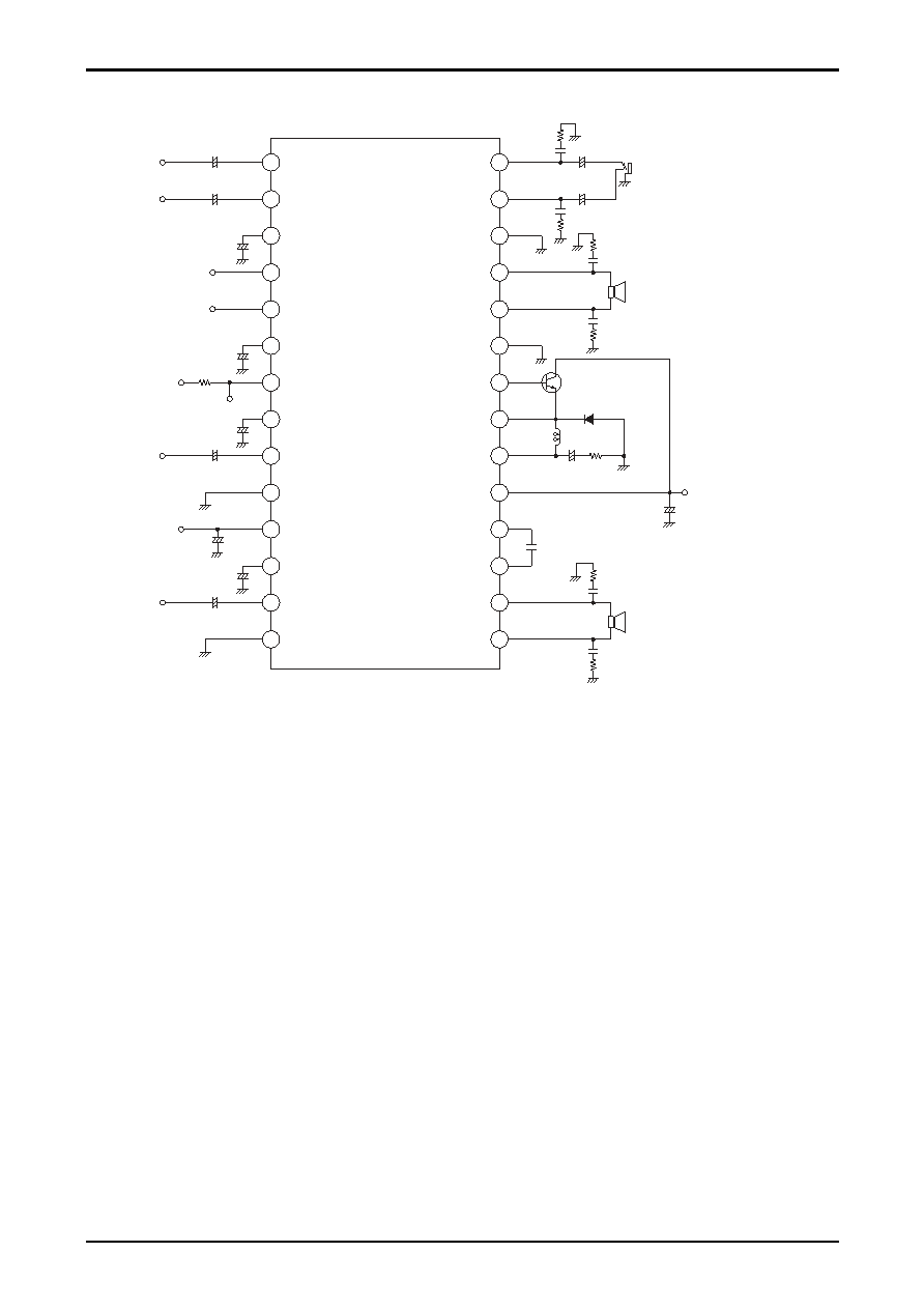
Test Circuit
External Components
Amplifier Block
C4 :
Ripple filter capacitor. We recommend a value of 47
F.
C5 :
Sets the amplifier turn-on delay time. We recommend a value of 22
F. (The turn-on delay time for
this value will be about 0.7 seconds.) While the speed with which the amplifier turns on can be
increased by reducing the value of this capacitor, this can result in impulse noise. We recommend
using a value of over 10
F.
C6 and C8 :
Input capacitors. We recommend a value of 22
F. Note that if modified, 3.3F or lower values
should be used due to the relationship with impulse noise.
C7 :
Input reference amplifier capacitor. The same value as that for C6 and C8 must be used.
C9 and C10 :
Oscillation prevention capacitors. We recommend using polyester film capacitors with excellent
thermal characteristics. These are used together with R1, R2, R3, and R4.
C14 and C15
C11 :
Switching regulator oscillation prevention capacitor. We recommend a value of 1000pF.
C12 :
Power supply capacitor
C13 :
Switching regulator output smoothing capacitor. The LA4919N adopts a self-excited switching
regulator technique. Since this capacitor influences the self excitation stability characteristics and
the regulator efficiency, we recommend using a capacitor with a low equivalent series resistance
and excellent thermal characteristics. For the same reason, resistor R5 (2.2
) is used together with
this capacitor.
C20 :
Pre-VCC power supply capacitor. This capacitor is not required when used connected to VCC.
1
28
2
27
3
26
4
25
5
24
6
23
7
22
8
21
9
20
10
19
11
18
12
17
13
16
14
15
HP IN1
HP IN2
HP D.C
HP Standby
AMP Standby
D.C
DDL
ON TIME
IN2
IN1
POWER GND
PRE GND
PRE VCC
IN VREF
HP OUT2
HP OUT1
POWER GND
OUT2-
OUT2+
SW GND
SWB
SWE
SW OUT
OUT1+
OUT1-
VCC
+B
0.1
F
+
++
+
R7 10
+
R5
2.2k
*C10 0.1
F
*C9 0.1
F
*DDL OUT
C12
1000
F/25V
C13
2.2
F/25V
C16
0.047
F
C17
0.047
F
C19 100
F/10V
C18 100
F/10V
Headphones
C11 1000pF
R2 2.2
*C14 0.1
F
L1 200
H
D1 Flywhool Di
R3 2.2
Tr1
Switching transistor
IC=2.5V
fT=30 to 50MHz
Components used during testing
- Tr1 : 2SD1667 (S rank)
- SANYO Electric Co., Ltd.
- D1 : SB10-05A2
- SANYO Electric Co., Ltd.
- L1 : A671HN-221L
- TOKO, Inc.
-C13 : OS capacitor
- SANYO Electric Co., Ltd.
R1 2.2
*C15 0.1
F
R4 2.2
R6 10
C1
1
F/10V
C3
47
F/25V
C4
47
F/25V
C5
22
F/6.3V
C7
22
F/6.3V
C20
10
F/25V
C2
1
F/10V
C6
2.2
F/6.3V
C8
2.2
F/6.3V
10k
*When measuring
DDL OUT, apply 5V
and measure through
a 10k
resistor.
* : When used shorted to VCC (pin 19),
it is not necessary to add a capacitor
at pin 11.
* : Polyester film capacitor
相關(guān)PDF資料 |
PDF描述 |
|---|---|
| LA5677M | 0.021 A SWITCHING CONTROLLER, 500 kHz SWITCHING FREQ-MAX, PDSO16 |
| LA5679T | 0.03 A SWITCHING CONTROLLER, 320 kHz SWITCHING FREQ-MAX, PDSO36 |
| LA6516 | 2 CHANNEL, AUDIO AMPLIFIER, PSFM10 |
| LA6524 | SPECIALTY CONSUMER CIRCUIT, PSFM10 |
| LA6530M | SPECIALTY CONSUMER CIRCUIT, PDSO30 |
相關(guān)代理商/技術(shù)參數(shù) |
參數(shù)描述 |
|---|---|
| LA4B-M1C2LV-G | 制造商:IDEC CORPORATION 功能描述:Switch Push Button N.O./N.C. DPDT Flush Rectangular Button 0.1A 250VAC 250VDC Momentary Contact PC Pins Panel Mount/Through Hole |
| LA4B-M1C2LV-W | 制造商:IDEC CORPORATION 功能描述:Switch Push Button N.O./N.C. DPDT Flush Rectangular Button 0.1A 250VAC 250VDC Momentary Contact PC Pins Panel Mount/Through Hole |
| LA4CA00 | 制造商:TE Connectivity 功能描述: |
| LA4CM00 | 制造商:TE Connectivity 功能描述: |
| LA4CM05 | 制造商:TE Connectivity 功能描述: |
發(fā)布緊急采購,3分鐘左右您將得到回復(fù)。