- 您現(xiàn)在的位置:買賣IC網(wǎng) > PDF目錄43902 > LA5635H SPECIALTY ANALOG CIRCUIT, PDSO28 PDF資料下載
參數(shù)資料
| 型號: | LA5635H |
| 元件分類: | 模擬信號調(diào)理 |
| 英文描述: | SPECIALTY ANALOG CIRCUIT, PDSO28 |
| 封裝: | 0.375 INCH, HSOP-28 |
| 文件頁數(shù): | 10/11頁 |
| 文件大小: | 144K |
| 代理商: | LA5635H |

LA5635H
No.64989-8/11
Continued from preceding page.
Pin No.
Pin nmae
Function
Equivalent circuit
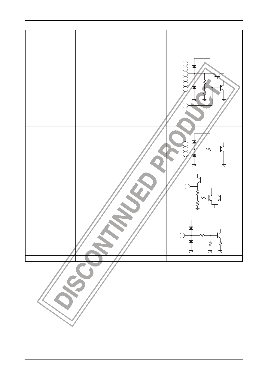
Stabilized 5V system and 8V system power supply outputs.
The on/off state of these systems is controlled by the serial
data.
Application examples
13
CN2
Pin 13: Insert a capacitor of about 1
μF between this pin and
pin 14 to improve the TAPE8V ripple rejection.
This pin controls the pin 14 output voltage. Set this pin to
about 7V by inserting a resistor between this pin and ground if
impulse noise from the Dolby IC occurs in cranking mode.
14
TAPT8V (8V, 30mA)
Pin 14: TAPE8V, Cassette tape etc.
15
ACC5V (5V, 100mA)
Pin 15: ACC5V, digital system 5V power supply
16
RD8V (8V, 150mA)
Pin 16: RD8V, Radio etc.
17
CD5V (5V, 300mA)
Pin 17: CD5V, CD player etc.
18
FM8V (8V, 100mA)
Pin 18: FM8V power supply for use with a band switch.
19
COM8V (8V, 200mA)
Pin 19: COM8V power supply for an electronic volume/tone
control circuit.
*: Note that the total Pd must not exceed the IC rating.
14
15
VCC
16
17
18
19
5.1k
Ω
8V:27k
Ω
5V:15k
Ω
13
22
23
25
CLK
DATA
LATCH
The serial data received over this serial interface controls the
outputs other than COM10V and VDD5V. It also controls the
on/off state of P1 to P4.
22
VCC
23
25
2k
Ω
24
TP1 (5V)
Monitors the power supply used for the internal logic circuits
(the CLK, DATA, and LATCH inputs and on/off control).
COM10V
24
15k
Ω
5.1k
Ω
2k
Ω
26
STBY
Controls the running/stopped state of this IC.
When low, only VDD5V operates. All other circuits are
stopped.
When high, only COM10V and VDD5V operate
unconditionally. All other outputs are controlled by the serial
data.
VCC
26
40k
Ω
40k
Ω
20k
Ω
Frame
GND
Connected to the IC substrate (lowest potential)
相關(guān)PDF資料 |
PDF描述 |
|---|---|
| LA5693D | 1-CHANNEL POWER SUPPLY MANAGEMENT CKT, PDIP8 |
| LA5693M | 1-CHANNEL POWER SUPPLY MANAGEMENT CKT, PDSO8 |
| LA8638NV | COMPANDER, PDSO30 |
| LA8638V | COMPANDER, PDSO30 |
| LANC4805UW12 | 1-OUTPUT 12 W DC-DC REG PWR SUPPLY MODULE |
相關(guān)代理商/技術(shù)參數(shù) |
參數(shù)描述 |
|---|---|
| LA5636M | 制造商:SANYO 制造商全稱:Sanyo Semicon Device 功能描述:DC/DC Converter Secondary Side Control IC |
| LA5640 | 制造商:未知廠家 制造商全稱:未知廠家 功能描述: |
| LA5640N | 制造商:SANYO 制造商全稱:Sanyo Semicon Device 功能描述:VOLTAGE REGULATOR FOR LCD |
| LA5641R11 | 制造商:未知廠家 制造商全稱:未知廠家 功能描述:Optoelectronic |
| LA5642R11 | 制造商:未知廠家 制造商全稱:未知廠家 功能描述:Optoelectronic |
發(fā)布緊急采購,3分鐘左右您將得到回復(fù)。