- 您現(xiàn)在的位置:買賣IC網(wǎng) > PDF目錄30723 > LA7425 SPECIALTY CONSUMER CIRCUIT, PDIP36 PDF資料下載
參數(shù)資料
| 型號(hào): | LA7425 |
| 元件分類: | 消費(fèi)家電 |
| 英文描述: | SPECIALTY CONSUMER CIRCUIT, PDIP36 |
| 封裝: | SDIP-36 |
| 文件頁(yè)數(shù): | 6/7頁(yè) |
| 文件大小: | 153K |
| 代理商: | LA7425 |

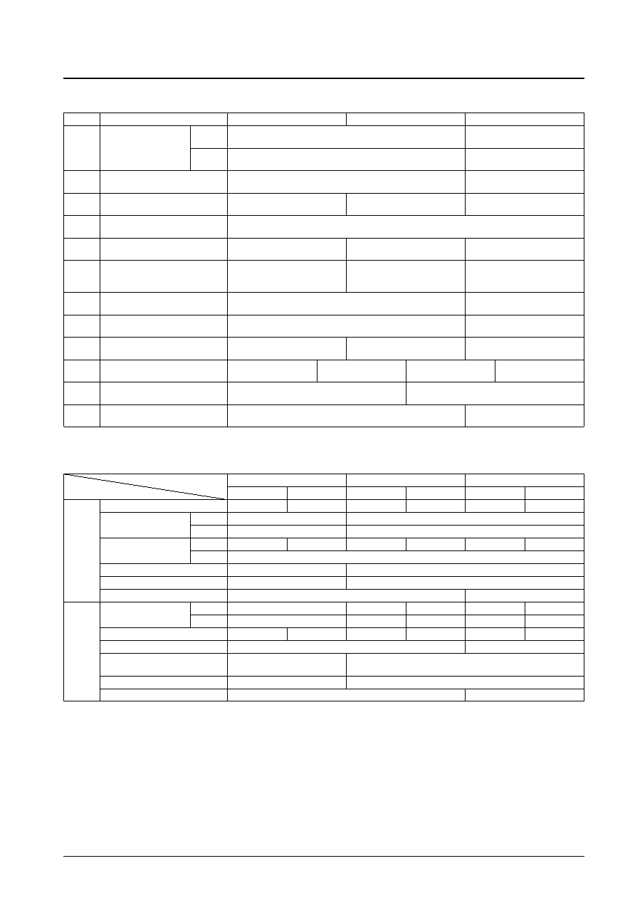
Control Pin Function Table
Note: Do not set pin 12 to a voltage of 1.5 V or lower, since the chip will enter test mode.
Mode Control Table
Note: CNR is not turned off in edit mode.
* The APC loop becomes post-comb when pin 16 is set high (trick mode).
No. 5110-6/7
LA7425
Pin No.
Control function
L
M
H
REC
Synchronization detector output when open.
3.6 V or higher
1
CNR adjustment
(0 V when synchronized, 3.0 V when not synchronized)
CNR adjustment mode
Forced NVHS control
PB
S-VHS detector output when open.
3.6 V or higher
(0 V in normal mode, 3.0 V for S-VHS)
Forced N-VHS mode
4
Record/playback switching
Open
3.8 V or higher
Record mode
Playback mode
7
SP/LP/EP switching
1.2 V or lower
1.8 to 2.7 V
3.3 V or higher
SP mode
LP mode
EP mode
11
If a 3.3 k
resistor is connected between pin 11 and ground, the playback mode SP YNR will be set to
strong (K = 0.5), and to very strong (K = 0.6) in LP/EP modes.
12
Edit/picture control
2 to 2.5 V
2.5 to 3 V
3.6 V or higher
Picture control: soft
Picture control: hard
Edit mode
Noise canceller control
1.5 V or lower
2.0 to 3.0 V
3.8 V or higher
13
Y/C mix off
Noise canceller: off
Noise canceller linear control
Y/C mix: off
(playback Y/C separate output)
16
APC loop switching
3.8 V or higher (200 A or higher)
(trick mode)
APC loop “post-comb”
21
3.5 V or higher
Record: XO: forced free-run
23
CNR control
1.5 V or lower
Open
2.5 V or higher
***
CNR: on
CNR: off
29
QV/QH insertion
0.8 V or lower
1.0 to 2.2 V
2.5 to 3.2 V
3.8 V or higher
Through
Character insertion
QH insertion
QV insertion
30
Rotary pulse input
1.2 V or lower
1.8 V or higher
Low CH
High CH
34
DOC stop control
Open
3.75 V or higher
Normal mode
DOC stopped
SP
EP
LP
Normal
Edit
Normal
Edit
Normal
Edit
Detail enhancer
Strong
Weak
YNR
K
—
0.65
LIMITT
—
5 IRE
REC
Y/C comb separator
C
O
—
O
—
O
—
Y
O
1/2 fH carrier shift
—
O
Nonlinear emphasis
—
O
Burst emphasis
O
—
YNR
K
0.2
0.5
0.2
0.5
0.2
LIMITT
5 IRE
11 IRE
5 IRE
11 IRE
5 IRE
Picture control
O
Center point
O
Center point
O
Center point
PB
Burst de-emphasis
O
—
Crosstalk cancellation
O
—
correlation switching
APC loop
Pre-comb*
Post-comb
Four phase shift clock
DPLL output
HHK output
相關(guān)PDF資料 |
PDF描述 |
|---|---|
| LA74300FN | SPECIALTY CONSUMER CIRCUIT, QCC28 |
| LA74302FN | AUDIO AMPLIFIER, QCC28 |
| LA74302FN | AUDIO AMPLIFIER, QCC28 |
| LA74303FN | SPECIALTY CONSUMER CIRCUIT, QCC24 |
| LA74303FN | SPECIALTY CONSUMER CIRCUIT, QCC24 |
相關(guān)代理商/技術(shù)參數(shù) |
參數(shù)描述 |
|---|---|
| LA74302FN | 制造商:SANYO 制造商全稱:Sanyo Semicon Device 功能描述:Monolithic Linear IC Audio Interface for DSC |
| LA74303FN | 制造商:SANYO 制造商全稱:Sanyo Semicon Device 功能描述:Monolithic Linear IC Audio Interface for DSC |
| LA74308LP | 制造商:SANYO 制造商全稱:Sanyo Semicon Device 功能描述:Monolithic Linear IC Audio Interface for DSC |
| LA74308LP_08 | 制造商:SANYO 制造商全稱:Sanyo Semicon Device 功能描述:Audio Interface for DSC |
| LA74309FA | 制造商:SANYO 制造商全稱:Sanyo Semicon Device 功能描述:Microphone Amplifier for Digital Still Camera |
發(fā)布緊急采購(gòu),3分鐘左右您將得到回復(fù)。