- 您現(xiàn)在的位置:買賣IC網 > PDF目錄367527 > LC3564SS-85 PDF資料下載
參數(shù)資料
| 型號: | LC3564SS-85 |
| 文件頁數(shù): | 6/9頁 |
| 文件大?。?/td> | 145K |
| 代理商: | LC3564SS-85 |

No. 5804-6/9
LC3564B, BS, BM, BT-70/10
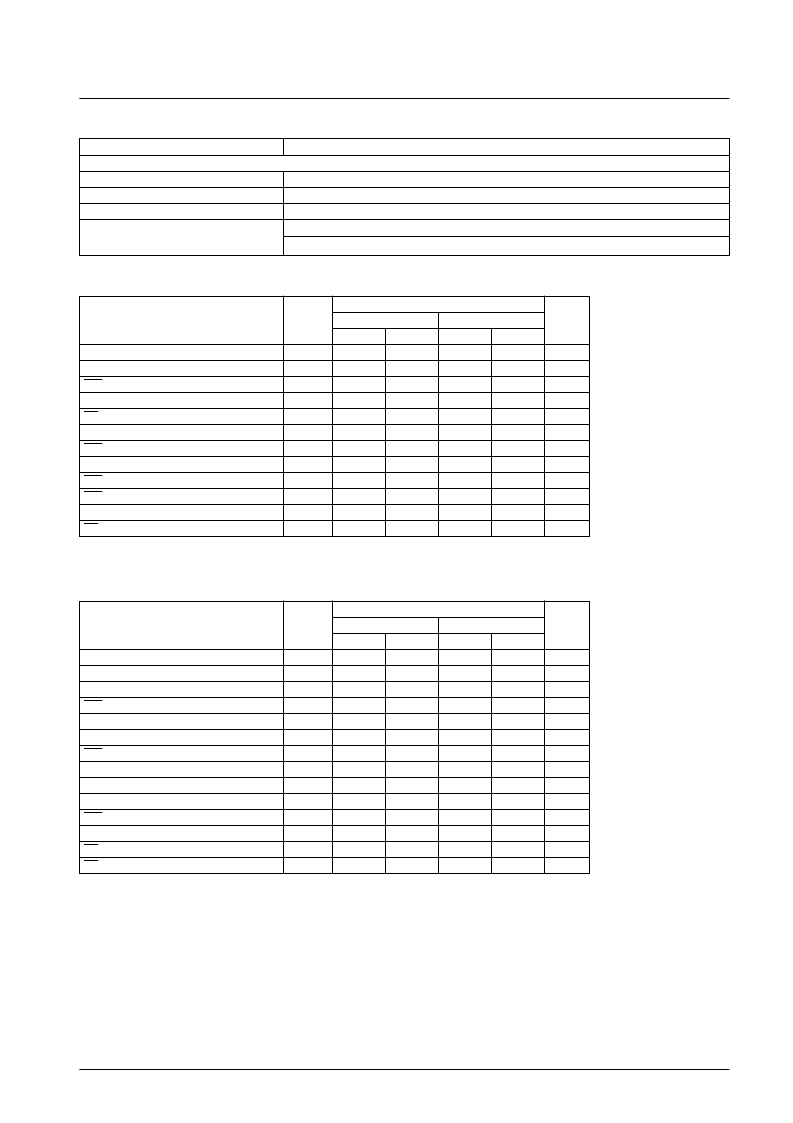
AC Electrical Characteristics
at Ta = –40 to +85°C, V
CC
= 2.7 to 3.3 V
LC3564B, BS, BM, BT
Parameter
Symbol
-70
-10
Unit
min
max
min
max
Read cycle time
t
RC
t
AA
t
CA1
t
CA2
t
OA
t
OH
t
COE1
t
COE2
t
OOE
t
COD1
t
COD2
t
OOD
200
500
ns
Address access time
200
500
ns
CE1 access time
200
500
ns
CE2 access time
200
500
ns
OE access time
100
250
ns
Output hold time
20
20
ns
CE1 output enable time
20
20
ns
CE2 output enable time
20
20
ns
OE output enable time
10
10
ns
CE1 output disable time
60
120
ns
CE2 output disable time
60
120
ns
OE output disable time
50
100
ns
Read Cycle
LC3564B, BS, BM, BT
Parameter
Symbol
-70
-10
Unit
min
max
min
max
Write cycle time
t
WC
t
AS
t
WP
t
CW1
t
CW2
t
WR
t
WR1
t
WR2
t
DS
t
DH
t
DH1
t
DH2
t
WOE
t
WOD
200
500
ns
Address setup time
0
0
ns
Write pulse width
140
200
ns
CE1 setup time
150
250
ns
CE2 setup time
0
250
ns
Write recovery time
0
0
ns
CE1 write recovery time
0
0
ns
CE2 write recovery time
130
0
ns
Data setup time
0
180
ns
Data hold time
0
0
ns
CE1 data hold time
0
0
ns
CE2 data hold time
10
0
ns
WE output enable time
10
ns
WE output disable time
60
120
ns
Write Cycle
Parameter
Conditions
[AC Test Conditions]
Input pulse voltage
V
IH
= V
CC
– 0.2 V, V
IL
= 0.2 V
10 ns
Input rise and fall times
Input and output timing level
1.5 V
Output load
LC3564B, BS, BM, BT-70 : 30pF (Including the jig capacitance.)
LC3564B, BS, BM, BT-10 : 100pF (Including the jig capacitance.)
相關PDF資料 |
PDF描述 |
|---|---|
| LC3564ST | |
| LC361000AMLL-10X | |
| LC361000AMLL-70 | |
| LC361000AMLL-70X | |
| LC361000ARLL(X) | |
相關代理商/技術參數(shù) |
參數(shù)描述 |
|---|---|
| LC3564ST | 制造商:未知廠家 制造商全稱:未知廠家 功能描述: |
| LC3564ST-10 | 制造商:SANYO 制造商全稱:Sanyo Semicon Device 功能描述:64K (8192 words x 8 bits) SRAM |
| LC3564ST-70 | 制造商:SANYO 制造商全稱:Sanyo Semicon Device 功能描述:64K (8192 words x 8 bits) SRAM |
| LC3564ST-85 | 制造商:SANYO 制造商全稱:Sanyo Semicon Device 功能描述:64K (8192 words x 8 bits) SRAM |
| LC35CN2 | 制造商:Dialight 功能描述:IN LENS 337 BASE CLR 09 3 |
發(fā)布緊急采購,3分鐘左右您將得到回復。