- 您現(xiàn)在的位置:買賣IC網(wǎng) > PDF目錄30730 > LC7219M PLL FREQUENCY SYNTHESIZER, 160 MHz, PDSO24 PDF資料下載
參數(shù)資料
| 型號(hào): | LC7219M |
| 元件分類: | PLL合成/DDS/VCOs |
| 英文描述: | PLL FREQUENCY SYNTHESIZER, 160 MHz, PDSO24 |
| 封裝: | MFP-24 |
| 文件頁(yè)數(shù): | 9/12頁(yè) |
| 文件大?。?/td> | 212K |
| 代理商: | LC7219M |

LC7219, 7219M
No.3661–6/12
Note
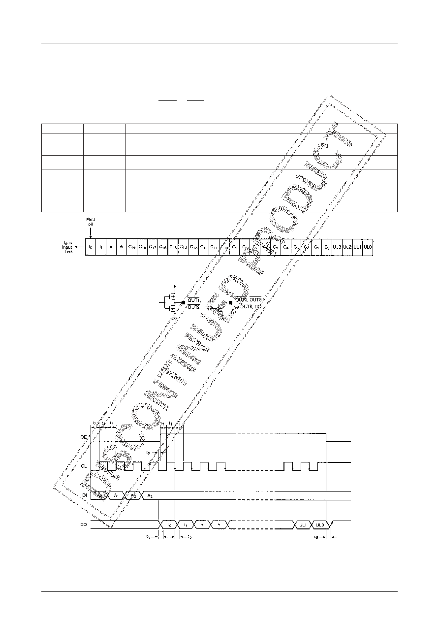
t1≥1.5s, t2≥0s, t3≥1.5s, t5<1.5s
Figure 3. Shift register data format
Serial Data Output
The LC7219 and LC7219M both have an internal 28-bit shift register that comprise two bits representing the state of
IN0 and IN1 (I0 and I1, respectively), a 20-bit general-purpose counter address (C0 to C19) and unlock flags (UL0 to
UL3) as shown in table 3.
The shift register contents are clocked out on DO when the serial data output mode is selected as shown in figure 3.
The internal circuit of outputs DO and OUT0 to OUT6 are shown in figure 4.
Table 3. Shift register data
s
t
i
Be
m
a
N
n
o
i
t
p
i
r
c
s
e
D
2
,
1I0 I
, 1
a
t
a
d
t
r
o
p
t
u
p
n
I
I0
d
n
a
,
0
N
I
f
o
e
t
a
t
s
e
h
t
s
iI1
.
1
N
I
f
o
e
t
a
t
s
e
h
t
,
4
,
3d
il
a
v
n
I
4
2
o
t
5C0
C
o
t
9
1
e
u
l
a
v
r
e
t
n
u
o
c
e
s
o
p
r
u
p
-
l
a
r
e
n
e
G
s
t
i
BC0
C
o
t
9
1
C
.
r
e
t
n
u
o
c
t
i
b
-
0
2
e
h
t
f
o
e
u
l
a
v
d
e
h
c
t
a
l
e
h
t
e
r
a
9
1
.
b
s
m
e
h
t
s
i
8
2
o
t
5
20
L
U
o
t
3
L
U
s
t
i
b
s
u
t
a
t
s
k
c
o
l
n
u
L
P
a
r
o
f
e
u
l
a
v
e
h
t
s
d
e
c
x
e
r
o
r
e
s
a
h
p
e
h
t
n
e
h
W
.
t
i
u
c
r
i
c
r
o
t
c
e
t
e
d
k
c
o
l
n
u
e
h
t
m
o
r
f
a
t
a
d
e
h
c
t
a
l
e
h
t
e
r
a
3
L
U
o
t
0
L
U
s
t
i
B
.
t
e
s
i
t
i
b
e
h
t
,
l
a
t
s
y
r
c
z
H
M
2
.
7
a
r
o
f
w
o
l
e
b
n
w
o
h
s
a
t
i
b
n
e
v
i
g
n
e
h
w
t
e
s
i
0
L
U
Φ
R
O
R
E
≥
s
1
.
1
n
e
h
w
t
e
s
i
1
L
U
Φ
R
O
R
E
≥
s
2
.
2
n
e
h
w
t
e
s
i
2
L
U
Φ
R
O
R
E
≥
s
3
.
3
n
e
h
w
t
e
s
i
3
L
U
Φ
R
O
R
E
≥
s
5
.
0
Figure 4. Output driver internal circuits
Serial Data Output Timing
The timing for the serial data output is shown in figure 5. Bits A0 to A3 are the mode select bits. When CE goes HIGH,
I0 is output on DO, and each subsequent data bit is output on the falling edge of CL. CE should be held HIGH for 27
clock cycles to allow all data to be output.
In serial data output mode, DO is forced HIGH when CE goes LOW as shown in figure 5. DO goes LOW when the
status of IN0 changes. In frequency or period measurement modes, DO goes LOW when frequency or period measure-
ment is completed.
Figure 5. Output timing
相關(guān)PDF資料 |
PDF描述 |
|---|---|
| LC7230-8221 | SPECIALTY CONSUMER CIRCUIT, PQFP80 |
| LC7230-8272 | SPECIALTY CONSUMER CIRCUIT, PQFP80 |
| LC72323-XXXX | SPECIALTY CONSUMER CIRCUIT, PQFP80 |
| LC723341E | SPECIALTY CONSUMER CIRCUIT, PQFP64 |
| LC723341E | SPECIALTY CONSUMER CIRCUIT, PQFP64 |
相關(guān)代理商/技術(shù)參數(shù) |
參數(shù)描述 |
|---|---|
| LC7220 | 制造商:未知廠家 制造商全稱:未知廠家 功能描述: |
| LC7221 | 制造商:未知廠家 制造商全稱:未知廠家 功能描述: |
| LC7222 | 制造商:未知廠家 制造商全稱:未知廠家 功能描述: |
| LC7223 | 制造商:未知廠家 制造商全稱:未知廠家 功能描述: |
| LC7225 | 制造商:未知廠家 制造商全稱:未知廠家 功能描述: |
發(fā)布緊急采購(gòu),3分鐘左右您將得到回復(fù)。