- 您現(xiàn)在的位置:買賣IC網(wǎng) > PDF目錄358762 > LC74760M (Sanyo Electric Co.,Ltd.) On-Screen Display IC PDF資料下載
參數(shù)資料
| 型號(hào): | LC74760M |
| 廠商: | Sanyo Electric Co.,Ltd. |
| 英文描述: | On-Screen Display IC |
| 中文描述: | 屏幕顯示芯片 |
| 文件頁數(shù): | 12/14頁 |
| 文件大小: | 178K |
| 代理商: | LC74760M |
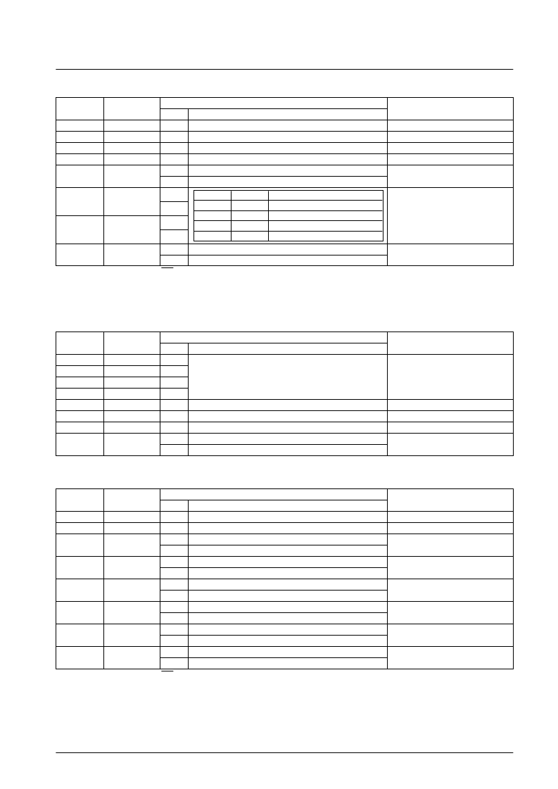
Second byte
Register content
DA0 to DA7
Register name
State
Function
Note
7
—
0
Second byte identification code
6
—
0
5
—
0
4
—
0
3
IOS
0
Sets the mode setting pin to be an input pin.
Switches the input/output direction of
the mode setting pins. (11 pin to 14 pin)
1
Sets the mode setting pin to be an output pin.
2
BCOL1
0
Determines whether a background color
is displayed. (Only valid in internal
synchronization mode.)
1
1
BCOL0
0
1
0
CBOFF
0
Outputs a color burst signal.
Only valid when either BCOL0 is 1 or
BCOL1 is 1.
1
Stops the output of color burst signals.
Note: When the chip is reset by the RST pin, the register states (bits) are all cleared to 0.
8
COMMAND7: Display Control Setting Command 4
First byte
Register content
DA0 to DA7
Register name
State
Function
Note
7
—
1
6
—
1
The command 7 identification code:
sets display control parameters.
5
—
1
4
—
1
3
—
0
2
—
0
1
—
0
0
LINS
0
Selects the lower 6 bits (bits 0 to 5)
Selects the upper or lower six bits when
halftone output line mode is specified.
1
Selects the upper 6 bits (bits 6 to B)
Second byte
Register content
DA0 to DA7
Register name
State
Function
Note
7
—
0
Second byte identification code
6
—
0
5
LIN5
0
Turns off (low) sixth line halftone output.
Used for the line 12 setting when LINS
is high.
1
Turns on (high) sixth line halftone output.
4
LIN4
0
Turns off (low) fifth line halftone output.
Used for the line 11 setting when LINS
is high.
1
Turns on (high) fifth line halftone output.
3
LIN3
0
Turns off (low) fourth line halftone output.
Used for the line 10 setting when LINS
is high.
1
Turns on (high) fourth line halftone output.
2
LIN2
0
Turns off (low) third line halftone output.
Used for the line 9 setting when LINS is
high.
1
Turns on (high) third line halftone output.
1
LIN1
0
Turns off (low) second line halftone output.
Used for the line 8 setting when LINS is
high.
1
Turns on (high) second line halftone output.
0
LIN0
0
Turns off (low) first line halftone output.
Used for the line 7 setting when LINS is
high.
1
Turns on (high) first line halftone output.
Note: When the chip is reset by the RST pin, the register states (bits) are all cleared to 0.
No. 4453-12/14
LC74760, 74760M
BCOL1
0
0
1
1
BCOL0
0
1
0
1
Background color
Background color displayed
No background color (about 15 IRE)
No background color (about 25 IRE)
Illegal value
相關(guān)PDF資料 |
PDF描述 |
|---|---|
| LC74761 | On-Screen Display LSI |
| LC74761M | On-Screen Display LSI |
| LC74763 | On-Screen Display LSI |
| LC74763M | On-Screen Display LSI |
| LC74770 | On-Screen Display Controller LSI |
相關(guān)代理商/技術(shù)參數(shù) |
參數(shù)描述 |
|---|---|
| LC74761 | 制造商:SANYO 制造商全稱:Sanyo Semicon Device 功能描述:On-Screen Display LSI |
| LC74761_11 | 制造商:SANYO 制造商全稱:Sanyo Semicon Device 功能描述:On-Screen Display LSI |
| LC74761M | 制造商:SANYO 制造商全稱:Sanyo Semicon Device 功能描述:On-Screen Display LSI |
| LC74761M-9006-E | 功能描述:顯示驅(qū)動(dòng)器和控制器 RoHS:否 制造商:Panasonic Electronic Components 工作電源電壓:2.7 V to 5.5 V 最大工作溫度: 安裝風(fēng)格:SMD/SMT 封裝 / 箱體:QFN-44 封裝:Reel |
| LC74763 | 制造商:SANYO 制造商全稱:Sanyo Semicon Device 功能描述:On-Screen Display LSI |
發(fā)布緊急采購,3分鐘左右您將得到回復(fù)。