- 您現在的位置:買賣IC網 > PDF目錄358765 > LC78628E (Sanyo Electric Co.,Ltd.) 16-bit fixed point DSP with Flash PDF資料下載
參數資料
| 型號: | LC78628E |
| 廠商: | Sanyo Electric Co.,Ltd. |
| 元件分類: | 數字信號處理 |
| 英文描述: | 16-bit fixed point DSP with Flash |
| 中文描述: | 具有閃存的 16 位定點 DSP |
| 文件頁數: | 13/40頁 |
| 文件大?。?/td> | 241K |
| 代理商: | LC78628E |
第1頁第2頁第3頁第4頁第5頁第6頁第7頁第8頁第9頁第10頁第11頁第12頁當前第13頁第14頁第15頁第16頁第17頁第18頁第19頁第20頁第21頁第22頁第23頁第24頁第25頁第26頁第27頁第28頁第29頁第30頁第31頁第32頁第33頁第34頁第35頁第36頁第37頁第38頁第39頁第40頁
No. 6329-13/40
LC78628E
MSB
LSB
Data
Command ($81 to $87, $DB, $DC, $D8)
MSB
LSB
RWC
CQCK
COIN
A12807
Two-byte commands (RWC set once)
Code
Command
RES = low
$FE
Command input noise reduction mode
$EE
Reset command input noise reduction mode
G
G
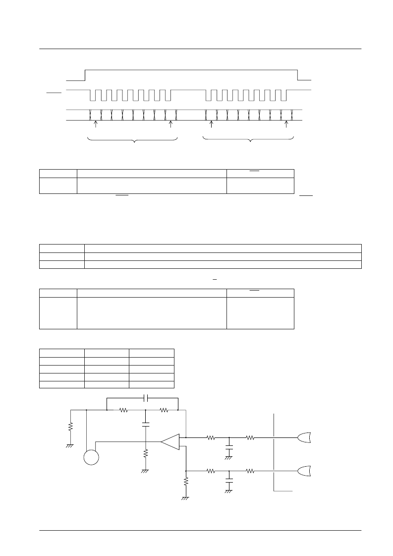
This command reduces noise on the CQCK signal. Although this command is effective for noise pulses of less than 500 ns, the CQCK timing parameters t
WL
,
t
WH
, and t
SU
must all be set to 1μs or longer.
Command noise reduction
Code
Command
RES = low
$04
Disc motor start (accelerate)
$05
Disc motor CLV (CLV)
$06
Disc motor brake (decelerate)
$07
Disc motor stop (stop)
G
G
The CLV
+
signal accelerates the disc in the forward direction, while the CLV
–
signal decelerates the disc. The corresponding mode, accelerate, decelerate,
CLV, or stop, is selected by the command sent from the microcontroller. The table below lists the CLV
+
and CLV
–
outputs in each of these modes.
6. CLV servo circuit — Pin 13: CLV
+
, pin 14: CLV
–
, pin 15: V/P
PCCL input level
Command transfer during track check, track jump, and internal motor braking operations
L
Incorrect operation occurs if a command is transferred (if a high level is applied to RWC).
H
Transfer of only the port related ($DBXX and $DCXX) and HDCD register setting ($D8XX) commands is allowed.
Mode
CLV
+
CLV
–
Accelerate
H
L
Decelerate
L
H
CLV
Pulse output
Pulse output
Stop
L
L
PCCL
The PCCL control pin is provided to allow the use of certain commands for which command transfer is disabled during
track check, track jump, and internal motor braking operations.
A12808
14
13
CLV–
CLV+
+
–
+
–
Disc motor
M
Note: The CLV servo control commands set the TOFF pin low during CLV mode, and high at all other times. The TOFF pin can only be controlled by
commands during CLV mode.
相關PDF資料 |
PDF描述 |
|---|---|
| LC78630 | 16-bit fixed point DSP with Flash |
| LC78630E | 16-bit fixed point DSP with Flash |
| LC78631 | 16-bit fixed point DSP with Flash |
| LC78631E | 16-bit fixed point DSP with Flash |
| LC78632 | 16-bit fixed point DSP with Flash |
相關代理商/技術參數 |
參數描述 |
|---|---|
| LC7863 | 制造商:SANYO 制造商全稱:Sanyo Semicon Device 功能描述:DIGITAL SIGNAL PROCESSOR FOR COMPACT DISC PLAYERS |
| LC78630 | 制造商:SANYO 制造商全稱:Sanyo Semicon Device 功能描述:Compact Disk Player DSP |
| LC78630E | 制造商:SANYO 制造商全稱:Sanyo Semicon Device 功能描述:Compact Disk Player DSP |
| LC78631 | 制造商:SANYO 制造商全稱:Sanyo Semicon Device 功能描述:Compact Disk Player DSP |
| LC78631E | 制造商:SANYO 制造商全稱:Sanyo Semicon Device 功能描述:Compact Disk Player DSP |
發(fā)布緊急采購,3分鐘左右您將得到回復。