- 您現(xiàn)在的位置:買賣IC網(wǎng) > PDF目錄30736 > LC7871NE SPECIALTY CONSUMER CIRCUIT, PQFP100 PDF資料下載
參數(shù)資料
| 型號: | LC7871NE |
| 元件分類: | 消費(fèi)家電 |
| 英文描述: | SPECIALTY CONSUMER CIRCUIT, PQFP100 |
| 封裝: | QFP-100 |
| 文件頁數(shù): | 8/19頁 |
| 文件大?。?/td> | 299K |
| 代理商: | LC7871NE |

Register 9 (VRAM display and control switching)
Data: lsb [----DDWW] msb.
The default is [----1001].
This register switches the display between the two VRAMs (primary memory and secondary memory) and also
sets the MGC access. (Disk command access is limited to PM access.) Note that these settings are only valid
when the register 0 command selection is set to 1 and VRAM is 512 kbytes. (The item 2 command will be
ignored and 16-color display used.)
DD = Display memory control (01: display PM, 10: display SM, 11: additive mix)
WW = MGC access memory control (01: work PM, 10: work SM, 11: work PM & SM)
Register 10 (Software reset, external sync on/off, test mode)
Data: lsb [TTT--YSR] msb.
The default is [000--000].
T = Test mode setting
R = Software reset, 0: Normal operation, 1: Reset
The display screen will be held until the next command is executed when a software reset is
performed.
S = 0: TRANS is initialized on a software reset.
1: TRANS is not initialized on a software reset.
Y = 0: Reset on HRESET and VRESET in external clock mode (SON = 1).
1: Reset on VRESET in external clock mode (SON = 1). (HRESET is unnecessary.)
Register 11 (subtitle vertical scrolling)
Data: lsb [---VVVVV] msb.
The default is [---00000].
The screen position can be scrolled vertically in units of the font height.
V = Vertical scroll distance (0 to 17 font heights.)
Register 12 (subtitle horizontal scrolling)
Data: lsb [--HHHHHH] msb.
The default is [--000000].
The screen position can be scrolled horizontally in units of the font width.
H = Horizontal scroll distance (0 to 49 font widths.)
Register 13 (TRANS setting, only valid when SON = 1)
Data: lsb [PSBBBBBB] msb.
The default is [11000000].
P = 1: Makes the PM TRANS setting valid. 0: Invalid (whole screen display)
S = 1: Makes the SM TRANS setting valid. 0: Invalid (whole screen display)
B = The BGC TRANS value
Register 14 (YS and TRANS output timing)
Data: lsb [----TTTT] msb.
The default value is [----0001].
T = The phase between the video signal and the YS and TRANS (digital output) signals in 70 ns units.
The value of T can be set to one of the ten values in the range 0 to 9. In NTSC mode, YS and TRANS will be
in phase with the RGB output when T = 0, and with the C output when T = 8 or 9.
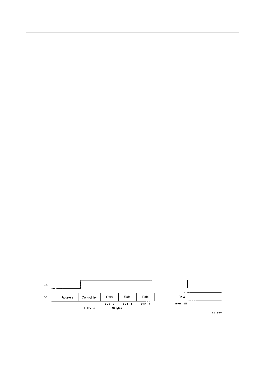
2. 19-byte command input (MGC write)
Address (F4h): lsb [00101111] msb
Control item:
lsb [1-------] msb
Data:
lsb [--WVUTSR] msb.
W to R are the subcode inputs.
Executed on the falling edge of the CE signal. Note that this operation cannot be executed during command
execution or when TIMER is 10 or 11.
No. 4861-16/19
LC7871E, 7871NE
相關(guān)PDF資料 |
PDF描述 |
|---|---|
| LC7872E | SPECIALTY CONSUMER CIRCUIT, PQFP64 |
| LC7874E | SPECIALTY CONSUMER CIRCUIT, PQFP64 |
| LC78835K | SPECIALTY CONSUMER CIRCUIT, PDIP24 |
| LC78835KM | SPECIALTY CONSUMER CIRCUIT, PDSO24 |
| LC78845Q | SPECIALTY CONSUMER CIRCUIT, PQFP48 |
相關(guān)代理商/技術(shù)參數(shù) |
參數(shù)描述 |
|---|---|
| LC7872E | 制造商:Panasonic Industrial Company 功能描述:IC |
| LC7874E | 制造商:SANYO 制造商全稱:Sanyo Semicon Device 功能描述:CD Graphics Decorder |
| LC7876E | 制造商:未知廠家 制造商全稱:未知廠家 功能描述: |
| LC7880 | 制造商:SANYO 制造商全稱:Sanyo Semicon Device 功能描述:16 bit D/A CONVERTER |
| LC7880M | 制造商:SANYO 制造商全稱:Sanyo Semicon Device 功能描述:16 bit D/A CONVERTER |
發(fā)布緊急采購,3分鐘左右您將得到回復(fù)。